Hi Panson - like Charlie I'm also happy to see more progress on this. I'm also running a project on TDA7293 at the moment. I found a couple of things out about the buffer which might interest you. Firstly remember that high open loop distortion you showed a while back? I think I found one of the reasons for it - the positive side gain is substantially less than the negative, giving large amounts of 2H. The fix I'm trying is to run bridged.
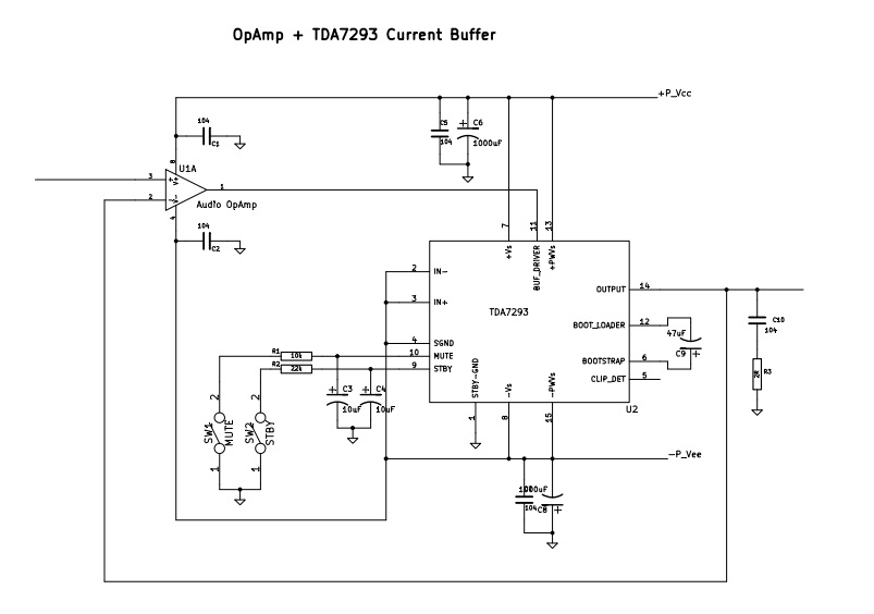
The second thing I noticed is the input impedance to the buffer (at pin 11) isn't high. I haven't explored this much further, but I wonder if its caused by the current source from the positive supply shown in the internal schematic. About 1.5mA seems to flow from the positive supply pin (pin7) to pin11. I plan to try an equal current source to the -ve supply to mitigate this.
The second thing I noticed is the input impedance to the buffer (at pin 11) isn't high. I haven't explored this much further, but I wonder if its caused by the current source from the positive supply shown in the internal schematic. About 1.5mA seems to flow from the positive supply pin (pin7) to pin11. I plan to try an equal current source to the -ve supply to mitigate this.
Hi Richard,
Long time no talk! Thank you for your TDA7293 information. Are you using it for a personal or commercial project? I guess if we spend time to "fully" understand these chip amps capabilities and limitations, we can make very good sounding amp. This is a difference between a standard app circuit with expensive components ($$$) and truly engineered circuit (brain, time).
Panson
Its a personal project which I'll make available for anyone who's interested, commercial or not. So its a bit like 'open source' except only for interested people rather than pushed out into the public domain. That is always assuming that it works! Yes, I am all for understanding these chips to our best abilities - your measurements certainly helped with that.
I do have one other suggestion for your earlier schematic, and it relates to power supply cleanliness. With the external opamp you have the option of much smoother supplies to it than is easy to achieve with the TDA7293's gain stage. While smoother supplies don't show up in sinewave testing I do have a hunch they contribute to better sound. You could try some LCLC filtering to the opamp's supplies.
I do have one other suggestion for your earlier schematic, and it relates to power supply cleanliness. With the external opamp you have the option of much smoother supplies to it than is easy to achieve with the TDA7293's gain stage. While smoother supplies don't show up in sinewave testing I do have a hunch they contribute to better sound. You could try some LCLC filtering to the opamp's supplies.
Hi Richard,
Thank you for your comment. I will try passive filtering and linear regulator.
Panson
Thank you for your comment. I will try passive filtering and linear regulator.
Panson
With the Parallel TDA7293 board, I'd be interested to set Both chips to slave mode and then drive the board with your voltage amp instead of the TDA7293's built in voltage amp.
Perhaps there would be an imaging improvement from using your external voltage amp to drive the TDA7293 power buffers.
Perhaps there would be an imaging improvement from using your external voltage amp to drive the TDA7293 power buffers.
abraxalito,
I am curious how thus bridged implementation turns out. I know you seem to prefer these chips over the National 3886 chips so I'll be watching to see how your experiment turns out. Still plugging away on my end.
I am curious how thus bridged implementation turns out. I know you seem to prefer these chips over the National 3886 chips so I'll be watching to see how your experiment turns out. Still plugging away on my end.
Hi Steven - I'm in two minds over which out of the 3886 and 7293 I prefer. If the output buffer alone gives decent results then the 7293 will be my pick but I prefer the front-end of the 3886 as its LTP is degenerated. If the buffer doesn't turn out viable (SQ-wise) then I plan to play with paralleling TDA1521s as the chip's very cheap here and I've had good results with other members of that family. They look to be AFAs.
Thanks for the rely Richard. Why do you prefer the paralleling of the devices rather than running these chips in a bridge configuration. I just looks simple though it may not be to run two chips in a bridged configuration with a buffer inverting one of the inputs. I'll keep and eye out for what you post. I was thinking to ask danielwritesbac if he has any final tweaked versions of a bridged circuit using any of these circuits. On the price differential between the TDA and National chips aren't the National 3886 chips fairly cheap in a final circuit?
It has been shown earlier in thread that paralleled operation has a lower THD.
The TDA7293/94 chips also have a higher supply voltage limit.
Paralleling them at the higher supply voltage allows for a higher output power at 8 ohms without the complications of a bridged configuration.
If you had two TDA7293 in parallel on about a +/- 58v it should theoretically produce 200watts into 8 ohms.
Although the data sheet does state about 80 watts for 1%THD (typically the start of clipping).
And of course a paralleled configuration makes it more tolerable for operation at lower impedance's and 4 of them in parallel would get you 400watts (320watts 1%THD) into 4 ohms for the same supply voltage.
FWIW
jer 🙂
P.S. I finally just got some of these chips to work with myself and I will be looking forward to seeing some more of your tests. 🙂
Last edited:
Why do you prefer the paralleling of the devices rather than running these chips in a bridge configuration.
My apologies, I omitted to mention I was planning to use the TDA1521s in bridged and parallel. Reason being they're limited to 42V max supply and about 2A repetitive peak current. So I was thinking 6 chips in total - three in parallel on each side.
On the price differential between the TDA and National chips aren't the National 3886 chips fairly cheap in a final circuit?
Here in China the LM3886s are significantly more expensive than the TDA7293s. The last batch of 7293s I bought as pulled ones as I ran into many re-labelled 94s as 93s so thought this route might be safer. They were about 70cents each from what I recall. The TDA1521s though are about 20cents.
As for the final circuit, I haven't costed up all the other parts - but I can't see why to spend more on dirty sand than its necessary 😛
Oooops, Sorry I missed the part about the TDA1521's
I have some TDA7393's that I was thinking about such a configuration as well although they are only good for supply of about 18-28V.
jer 🙂
I have some TDA7393's that I was thinking about such a configuration as well although they are only good for supply of about 18-28V.
jer 🙂
Thanks for the replies Richard and Gerald. I understand what you are doing there Richard the best of both things, parallel and bridged in one unit/ Seems then you would both have your power and be able to handle low impedance loads at a reasonable power level with good heat dissipation and low thd.
Gerald,
Those high power numbers above 1% distortion I normally just ignore as not really useful for anything but advertisement purposes. Even 1% in anything but a sub-woofer application I wouldn't typically look at as useful. From what I understand pushing any of these monolithic power chips up to the high voltage limits just ask for high distortion and in the case of the National chips with internal Spike protection circuits massive distortion when this protection kicks in.
Yes, I generally ignore them too, I was using the advertised figure at the headline of the data sheet at First.
Then I remembered that the actual non clipping figures are much less.
I have measured my amps while watching the waveform and 1% is right at or just above where the amp is hitting the supply rail.
Even though it looks ugly on a scope I was hard pressed to hear it at those levels.
Those levels are basically only for music peak references as they are typically 10db higher than music's constant RMS level.
The Spike level to my my understanding is triggered from heat as a function of current flowing through the output stage.
So, Yes more heat is generated for the same amount of current at a higher supply voltage even though the output power is the same.
Paralleled amps help to minimize this problem by reducing the flow of current per chip.
In my example I was using 8ohms as a load to explain the benefits of parallel operation at a high supply voltage.
As the impedance goes up you need a higher voltage swing in order to maintain the same power level.
If you are designing for a lower impedance (4 ohm or less) then it is advisable to use a lower power supply voltage.
A higher voltage swing is required for such application as driving ESL's which have a very wide impedance range.
They can have as much as a 100ohm impedance and as well as down to 1ohm across their bandwidth depending on the setup.
In which case a highly paralleled (4 chips or greater) configuration with the higher voltage supply would benefit and save the chips from failing.
Even some Dynamic systems can have impedance peaks as high as 30 to 80 ohms at times.
jer 🙂
Last edited:
Gerald,
Thanks for the answer and explanation for your choices. I have to say I am not up much on panel speakers and I can imagine that things are very different than normal dynamic speakers. As to those impedance rises in a dynamic speaker that can be ameliorated with a good impedance matching tank circuit so isn't much of a problem, but drops in the minimum impedance can be a problem. I am working on some 4ohm speakers so that is a concern for what I am doing. The bridged parallel circuit seems to be a workable solution ot both low distortion and high current and voltage output. It does seem in most of the circuits I have seen discussed that after the third monolithic chip is added keeping the current draws equal can become a problem and some thought must go into keeping things somewhat balanced so any one chip amp won't go into thermal distress with a higher load than the others. The National data sheet notes on this do talk about some of the problems with the bridged/parallel circuit but I have read that their solution is not complete and it needs additional help in the circuit to make it right. I would love to see this all worked out with either the TDA or National implementations.
Thanks for the answer and explanation for your choices. I have to say I am not up much on panel speakers and I can imagine that things are very different than normal dynamic speakers. As to those impedance rises in a dynamic speaker that can be ameliorated with a good impedance matching tank circuit so isn't much of a problem, but drops in the minimum impedance can be a problem. I am working on some 4ohm speakers so that is a concern for what I am doing. The bridged parallel circuit seems to be a workable solution ot both low distortion and high current and voltage output. It does seem in most of the circuits I have seen discussed that after the third monolithic chip is added keeping the current draws equal can become a problem and some thought must go into keeping things somewhat balanced so any one chip amp won't go into thermal distress with a higher load than the others. The National data sheet notes on this do talk about some of the problems with the bridged/parallel circuit but I have read that their solution is not complete and it needs additional help in the circuit to make it right. I would love to see this all worked out with either the TDA or National implementations.
There are couple of really good threads based on the LM3886 in a highly paralleled configuration and the use of the DCservo opamp circuit used inorder to keep the chips in balance with each other.
It was in 2010 if you do a search on the LM3886 and Paralleled Chipamp's.
I just recently re-posted the links but I forget which thread it was.
I am sure that this can be applied the the TDA7293/94's as well.
But the nice thing about the TDA's is the ability to add more chips using only one of them as a driver for all of the output stages is already implemented on them.
This is something that intrigues me as well and was touched upon in this thread.
Somewhere I saw a schematic of 3 or 4 of the TDA's wired in this fashion but no spec's on their ultimate performance using this technique was included.
Here is one thread of many,
http://www.diyaudio.com/forums/chip...e-no-lossy-emitter-resistors.html#post3004987
The schematic I saw was the same as that in the above post but with more output stages hooked up in parallel with maybe some resistor changes or something but nothing else was different about the configuration.
I hope to see more about this as well, I will look again for those other links for you as they are very interesting.
jer 🙂
P.S. Here is the link to the 2 links I had mentioned,
http://www.diyaudio.com/forums/chip-amps/153705-lm3886-parallel-output-resistors.html#post3474923
Cheers!! 🙂
Last edited:
Thanks again Gerald,
I have read some of those threads but there are so many it is hard to find the good from the bad in some of them. If you find what you are referencing that would be great. I can see how the TDA chips with that integration of driver and slave chips would make things easier to do. I wish that National had done something like this but I don't think that they intended for this type of high output beyond what they had done initially and I guess the volume sales never made them go any farther than they did with what they made.
Steven
Check my P.S. in my last post.
Here is another one,
http://www.diyaudio.com/forums/chip-amps/194511-lm3886-parallel.html#post2669624
Here are a couple discussing the DCservo,
http://www.diyaudio.com/forums/chip-amps/107246-dc-servo-question.html#post1283350
http://www.diyaudio.com/forums/chip-amps/103308-pa100-dc-servo.html#post1229583
jer 🙂
Sorry, if I have gone OT on this thread, Carry on !!! 🙂
- Status
- Not open for further replies.
- Home
- Amplifiers
- Chip Amps
- TDA7293 single, bridge, parallel