Looks great. FYI the TP Rev C board is a good example of smooth routing. I just opened up my ref C to do the compensation mod you PMed me.
Thanks
")
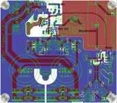
Yes, TP PCB are a good example but with groundplanes you must pay more attention if you want to use microstrips, gently mitered traces with 45° bends mantains constant impedance better...
Let me know what do you think of the alternate compensation.
Looks like you have already got a good grasp of this software, and I'm impressed.
Thanks, Tom
The design is looking really good for ease of building because it is much less cluttered than your previous attempts.
Yes, I agree...BTW the 100x80 version it's not so cluttered in my opionion
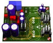
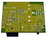
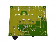
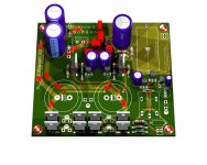
I've attached some render of it.
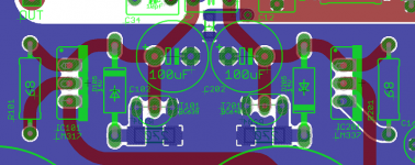
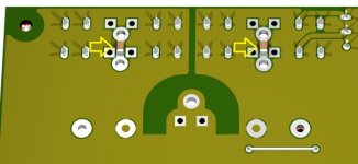
Now that the board is bigger, is there room enough to lay the resistors near the regulators down instead of standing them upright?
Sure, it can... see the attached detail.
But traces are longer and a litlle slot is made to the ground plane, any opinion on it?
Can you make a little more room around the 318? It looks pretty tight for the caps nearby.
This is more difficult, giving more space between caps would lead to longer traces where lenght is most critical.
BTW I've chosen caps that are big enough to accomodate a quite large set of alternatives.
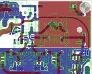
Perhaps some of the traces with large radius should be straightened again to make the path shorter. I'm not sure what is really gained by using such large curves, but I think a shorter path is always better. Other than extra length, I do like curves.
Can you be more precise? Exactly, to which traces are you referring to?
I was also wondering whether it's worth allowing for a larger C13 on board.
When I've started designing the larger board it was one of my goals but the Zn, or similar caps, are way too big to be placed on that board... the Hobbyst Edition allows 100x160 PCBs, unless people is willing to pay me the upgrade to the Professional Edition (840€)...

See the attachment.
Jokes apart it would require enlarging the PCB 2cm more with added cost in production, I would consider it if the PCB should be enlarged for additional circuits, like a second current pump...
But that's a whole new story... The PS would need to be redesigned.
Attachments
Last edited:
With my normal practice, I changed only one channel first. Initial impression is that the sound is not as dynamic. It is dryer. I will measure it some time in the next few days to compare the channels and see how they differ. My instinct is the phase is either going to lag a bit more at the high frequency or we might see some ringing at the top end. I will post more in the other thread. My speaker impedance is probably flat around 6Ohm if I remember correctly.
100x160, the cap will not fit if you make the board longer?
100x160, the cap will not fit if you make the board longer?
Last edited:
With my normal practice, I changed only one channel first. Initial impression is that the sound is not as dynamic. It is dryer. I will measure it some time in the next few days to compare the channels and see how they differ. My instinct is the phase is either going to lag a bit more at the high frequency or we might see some ringing at the top end. I will post more in the other thread. My speaker impedance is probably flat around 6Ohm if I remember correctly.
I'm curious to see your measurements...
100x160, the cap will not fit if you make the board longer?
Sure, I thought I've already stated it:
Jokes apart it would require enlarging the PCB 2cm more with added cost in production, I would consider it if the PCB should be enlarged for additional circuits, like a second current pump...
Beta testers needed
After last mods:
I think the PCB is ready for the prototype testing.
To keep costs reasonable and to have some real feedback I need 5 braves that will share the beta test with me (total 6 kits).
It would be nice if at least one or two partecipants have the knowledge/possibility to make some measurements (THD, stability, etc.).
Each beta tester will receive two blue 100x110mm PCBs (2mm FR4, 2Oz/70u) at 29€ (ca 39 US$) and possibly a partial kit (SMD parts + Elna RJHs+Wima FKS2s) at a price yet to be determined.
While I'm confident that the amps will work as intended from the start who choose to partecipate must be aware that it's possible that the amps may have problems or even don't work at all.
The price is for untested PCBs, if we want the electric test price is 37€
If the packet is less than 350g, shipping by Registered Mail will be:
Europe 9.50€
Worldwide (except Oceania) 12.50€
Tomorrow I'll post the BOM.
After last mods:
- space on-board for C13
- optional SMD caps for AC input
I think the PCB is ready for the prototype testing.
To keep costs reasonable and to have some real feedback I need 5 braves that will share the beta test with me (total 6 kits).
It would be nice if at least one or two partecipants have the knowledge/possibility to make some measurements (THD, stability, etc.).
Each beta tester will receive two blue 100x110mm PCBs (2mm FR4, 2Oz/70u) at 29€ (ca 39 US$) and possibly a partial kit (SMD parts + Elna RJHs+Wima FKS2s) at a price yet to be determined.
While I'm confident that the amps will work as intended from the start who choose to partecipate must be aware that it's possible that the amps may have problems or even don't work at all.
The price is for untested PCBs, if we want the electric test price is 37€
If the packet is less than 350g, shipping by Registered Mail will be:
Europe 9.50€
Worldwide (except Oceania) 12.50€
Tomorrow I'll post the BOM.
Attachments
Last edited:
Dario, I think your PCB looks great, I'm following this thread since the beginning, and I will, if PCB ends in group buy definitely build some. For the verification phase I think I don't have enough experience for troubleshooting or measurements.
I have a question regarding the PCB itself, I don't see that PCB is using any terminal blocks or terminal lugs for connecting AC wires to board ? Any special reason for that? sometimes its easyer to work with wires if you can disconnect them without desoldering.
Keep up the good work.
I have a question regarding the PCB itself, I don't see that PCB is using any terminal blocks or terminal lugs for connecting AC wires to board ? Any special reason for that? sometimes its easyer to work with wires if you can disconnect them without desoldering.
Keep up the good work.
Aren't those between the rectifiers?...
I have a question regarding the PCB itself, I don't see that PCB is using any terminal blocks or terminal lugs for connecting AC wires to board ? Any special reason for that? sometimes its easyer to work with wires if you can disconnect them without desoldering.
Keep up the good work.
Dario, I think your PCB looks great, I'm following this thread since the beginning,
...
I have a question regarding the PCB itself, I don't see that PCB is using any terminal blocks or terminal lugs for connecting AC wires to board ?
...
Keep up the good work.
Thanks Maxim
As Soongsc already noted there are both fast-on and cable connection for each AC input and speaker output.
Also signal input and led output are designed for Molex connectors.
Seems interesting. If you can take PayPal, I'd try a set.
Great Soongsc!
So at the moment:
- Me
- Soongsc
- .
- .
- .
- .
In this moment I'm doing the last tests (LM3886 ground to GND and optional caps for AC input) and preparing the BOM.
Dario, Count me in. May be a good excuse to buy some of the new "scope" hardware/software Android/iPhone offerings.
One question, do you recommend two boards/kits to be able to hear the improvements in "stage" and separation elements or can one grasp the differences that you are promoting with a single?
Will remit as required.
One question, do you recommend two boards/kits to be able to hear the improvements in "stage" and separation elements or can one grasp the differences that you are promoting with a single?
Will remit as required.
Dario, Count me in. May be a good excuse to buy some of the new "scope" hardware/software Android/iPhone offerings.
The measurement thing is a nice plus but it's not required.
So at the moment:
- Me
- Soongsc
- BmcBob
- .
- .
- .
One question, do you recommend two boards/kits to be able to hear the improvements in "stage" and separation elements or can one grasp the differences that you are promoting with a single?
One of the biggest difference will be soundstage, I think is hard to appreciate the change without two PCBs.
IMHO, the best thing is to buy the two PCBs since they will be manifactured with same specs as definitive ones:
- 2mm FR4
- 2 Oz/70u copper
- Blue solder-mask
- Serigraphy on both sides
- ROHS HASL finish
Anyway with two boards, if everything works as intended, you'll have a complete working amp.
Will remit as required.
It will be between the last week of December and the first of January since the PCB factory is closed for Christmas Holidays till Juanuary the 8th.
In this moment I'm doing the last tests (LM3886 ground to GND and optional caps for AC input)
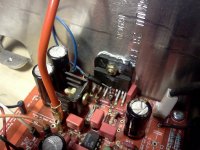
Wow, I was no expecting such a big impact.
Bass is tighter, soundstage wider and deeper and dynamic gains too, even the output DC offset fall near 0V (from 2mV to 0.5V in one channel).
The AC input caps have also a clear effect, without them bass is deeper and fuller and soundstage wider and deeper too.
The optional AC caps will remain since they permit more flexibility with different transformers and with the double bridge things could be different.
With these tests all mods included with FE are verified on TP boards apart the double diode bridge (BTW the PCB can be easily adapted to work also with a single bridge).
If the PCB works as intended this is going to be a pretty different beast...
Attachments
Last edited:
What AC caps are you referring to?
MyRef C had the Lm3886 ground to GND, you said that this board had the Lm3886 ground to signal ground. So which are you referring to as the WoW?
Well, let make thing clear...
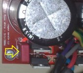
The 'AC' cap is marked C5 on TP boards, it's the one on side of rectifiers.
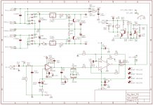
The original MyRef has the LM3886 GND (Pin 7) referred to 0V (signal ground) while the Fremen Edition to GND (power ground).
The wow is obviously referred to Fremen Edition way...
I've attached also the last schematic.
Attachments
Last edited:
Those AC caps are supposed to be X caps, are there surface mount Xcaps available? I wasn't aware of any, but I wasn't looking either.
Those caps are not specced as X type in none of My_Ref versions, actually I don't think they need to be... they're not on mains voltage.
I've always wondered about the LM3886 ground, but had not tried it yet.
Definitely that mod has a bigger effect than what I was expecting...
I would have expected larger caps for those though.
C5 was there only to damp ringing of the original diode bridge.
With the use of high speed/softrecovery discrete diodes it's no longer necessary, in fact in the My_Evo C5 is no longer present.
- Status
- This old topic is closed. If you want to reopen this topic, contact a moderator using the "Report Post" button.
- Home
- Amplifiers
- Chip Amps
- My_Ref Fremen Edition - need help on PCB evaluation