... try Dario's recommeded switch of R1 and R4 from the Dale metal films supplied in the kit to KOA SPR3 carbon film.
I can confirm Tom's observation that CFRs at R1, R4 remove most of the edge off the upper mids.
I switched to 2W CFRs a while ago after experimentation. However, most values of KOA aren't available locally, so I went with the local Watts brand, which is fine - except that the resistor body is slightly magnetic. The leads and end-caps are non-magnetic, though, and it is nevertheless better than both metal-oxide and metal-film at this location.
I haven't tried them, but carbon compositions may be even better, if you can find 2W values that fit.
If I remove the large capacitors from the RevC board and add leads to them, to make them fit into my enclosure, will it have any noticeable effect on the sound?
If you want to do that, it's recommended to move the bridge rectifier and snubber also off-board onto a separate PSU board on which the capacitors are mounted. That way, the large charge/discharge currents through the rectifier and caps can be isolated and restricted to a relatively short trace length on that PSU board, and the leads to the MyRef will only have to carry DC and (some of) the speaker-return current. You'll also have to move the rectifiers for the protection relay to the PSU board.
Grounding
Some more questions to aid my understanding of the circuit/boards.
First I notice there are only two outputs for ground: OGND and PGND. I assume OGND is for the "cold" speaker terminal, whilst PGND is for attaching to the safety earth, either by directly attaching to the same mounting point for mains safety or via another moutning point that ensures a conductive path is present between PGND and mains safety. Are these assumptions correct?
Second, I notice there is no output to allow all signal grounds to be connected together for both of the amplifier boards. I am assuming that star grounding has been built into each board for all the signal grounds for that channel, but I can't see a way for bringing both channels together such that they have a common signal ground that can then be earthed to the chassis. How is this achieved?
Thanks
First I notice there are only two outputs for ground: OGND and PGND. I assume OGND is for the "cold" speaker terminal, whilst PGND is for attaching to the safety earth, either by directly attaching to the same mounting point for mains safety or via another moutning point that ensures a conductive path is present between PGND and mains safety. Are these assumptions correct?
OGND is the Speaker return terminal.
PGND is actually the transformer 0 V terminal, not safety earth.
If you want to use a Safety Earth, connect a CL60 thermistor/isolator between PGND and the Chassis star ground.
Second, I notice there is no output to allow all signal grounds to be connected together for both of the amplifier boards. I am assuming that star grounding has been built into each board for all the signal grounds for that channel, but I can't see a way for bringing both channels together such that they have a common signal ground that can then be earthed to the chassis.
There's no need to connect the signal grounds to the chassis - in fact, you might potentially create conditions for a ground loop if you do that.
Simply connect each signal ground to the shield of the shielded cable from the RCA connector. If there's only one ground terminal at the RCA connector block, this will short the signal ground from each board at the RCA connector block.
So far, I have not seen any problems with this arrangement, though there is still a ground-loop that can arise from the individual shields of the signal cable from the audio source to the RCA connectors. The two shields are in close proximity, so the stray AC frequency magnetic field lines cannot induce much voltage in the enclosed area between the two shields. A low-amplitude, barely-audible hum cannot be ruled out.
Last edited:
So is signal ground "floating"?
The signal ground is "lifted" from PGND through a 1-ohm isolator on each board. If PGND is floating (not tied to the chassis), then the signal ground will also float.
In my latest round of modest modifications, I added a CL60 between the PCB PGND and safety AC ground inside each monoblock chassis. Both amps hummed at a low level, barely audible from my listening position. I removed the CL10's and the hum disappeared from both amps.
I will not compromise the otherwise stone silent performance of these amps to add the safety feature of PGND tied to the AC safety ground. That is a choice each builder must make for himself. Electricity is dangerous, but it's not evil. I, personally, do not envision the likelihood of mains AC ever finding its way through the circuit onto the speaker posts or RCA jacks. I have no toddlers or pets in my household. The chassis itself is safely grounded, and that's good enough for me. In the remotely possible event that I die from electrocution by touching the input or outputs of a catastrophically failed, powered amplifier, I will die happy, knowing that I heard these amps at their best.
Still, I recommend including the CL10 or some other method of tying the amps to safety ground. If you can do so without inducing hum, you are fortunate and can feel secure knowing you have eliminated one unlikely but potentially fatal hazard in a world filled with them.
And why on earth (ha ha) would you want to tie signal ground to the chassis?
Peace,
Tom E
Last edited:
I was intending to connect safety earth to chassis. P GND will be just the two secondaries of my trafo to create 0V. O GND will run to my (insulated) binding bost. Input GND from RCAs will be connected to a star point that will, in turn be connected to the safety earth with a single run. Notwithstanding the comments above about ground loops, I wish to replicate the absolute absence of hum when I have been testing the amps on my slab of wood testbed.
Cheers
Jon
Cheers
Jon
I'm trying to ID the Wima caps I have with the group buy, but am struggling to be sure I have them ID's correctly. Could someone please confirm if what I have said below is correct:
C32 150pf - the Wima cap with 150/100 printed on it
C21 22pf - the Wima cap with 0,022 printed on it
c7 100nf - the Wima cap with 1000/100 printed on it
C30 1nf - the Wima cap with u1J100 printed on the top of it.
Thanks
C32 150pf - the Wima cap with 150/100 printed on it
C21 22pf - the Wima cap with 0,022 printed on it
c7 100nf - the Wima cap with 1000/100 printed on it
C30 1nf - the Wima cap with u1J100 printed on the top of it.
Thanks
This is 22 nF, not pF - which is fine for C21.C21 22pf - the Wima cap with 0,022 printed on it
c7 100nf - the Wima cap with 1000/100 printed on it
C30 1nf - the Wima cap with u1J100 printed on the top of it.
These are interchanged - 1000/100 is C30: 1nF/100V; u1J100 is C7: 100nF/100V/5%..

Linux I keep sending folks your way for boards. Maybe 2 in the last month or so. Are you still holding approx 40 pcbs?
Uriah, thanks for the referrals - I have sold about 12 monoblock kits and a few bare boards to North American buyers, some of whom must be your referrals.
Yup, I have around 30-40 PCBs, but only about half of them are from your Chinese vendor. I can order additional boards from my Indian vendor(s) with about 3-4 weeks lead time - I have a re-spin in the works which allows more component flexibility (a few larger caps and resistors will fit). I'll post the Eagle layout and schematic when it's all cleaned up and taped-out.
Awesome! Glad you keep revising and improving. Certainly is worthwhile.
I agree with Uriah. You are doing very good work with it.
Just for curiosity, are there any pictures of them?Uriah, thanks for the referrals - I have sold about 12 monoblock kits and a few bare boards to North American buyers, some of whom must be your referrals.
Yup, I have around 30-40 PCBs, but only about half of them are from your Chinese vendor. I can order additional boards from my Indian vendor(s) with about 3-4 weeks lead time - I have a re-spin in the works which allows more component flexibility (a few larger caps and resistors will fit). I'll post the Eagle layout and schematic when it's all cleaned up and taped-out.
Just for curiosity, are there any pictures of them?
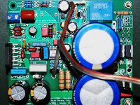
Here's an assembled Rev C Version 1.3 board, with 35mm diameter PSU caps.
Attachments
- Status
- This old topic is closed. If you want to reopen this topic, contact a moderator using the "Report Post" button.
- Home
- Amplifiers
- Chip Amps
- MyRefC build guide