Thanks Andrew, always vigilant regarding safety!
I appreciate the importance of safety earth with home made equipment. I want to stay alive (and I am naturally nervous) so I have made a secure earth available at my listening area and throughout my workshop. All earth connections and terminals properly and securely crimped (and soldered as well), as are all earth connections/terminals inside all my recent home made gear. I had to drill a small hole in the floor to tap an earth point outside the house...
I don't have a high voltage dielectric withstand tester (I know where I can rent one) as required by local code for safety testing manufactured double insulated electrical appliances.
In any case I need the earth to reduce noise.... Most professionally made audio gear here has an earth point on the back for voluntary earthing.
This amp is really starting to sound nice IMHO, many thanks to Uriah and to Sonidos (for helping Uriah pack the kits up last April). Thanks to Regi Regi and thanks also to all who's advice has helped me put this together (finally).
Bill
Last edited:
this does not sound right.I appreciate the importance of safety earth with home made equipment. I want to stay alive (and I am naturally nervous) so I have made a secure earth available at my listening area and throughout my workshop. All earth connections and terminals properly and securely crimped (and soldered as well), as are all earth connections/terminals inside all my recent home made gear. I had to drill a small hole in the floor to tap an earth point outside the house...
the last sentence tells me you have created a earth grounding point in the soil under your house.
I know this does not comply with UK codes. Is there an Electrical Engineer, or Electrical Technician listening. Can such a soil grounding point be made safe?
Have you tried measuring the resistance from Neutral to your soil grounding point?
Have you tried measuring the variation of this resistance over the seasons?
Does the soil ground end up at the same potential as the neutral when lightning strikes nearby?
Last edited:
Misunderstanding
Andrew,
I believe you have misunderstood me.
I would like to clarify...
At no point do I say anything about making an earth grounding point in the 'soil' under my house. Where did you get that idea from?
I took a suitable earth wire through the floor to connect to protective earth at an external (JET certified, weatherproof) AC mains socket.... this being the nearest reliable protective earth point. Japanese codes are very strict and I feel protected by them even though I am not a qualified electrical engineer, and do not fully understand the code.
Our home is seven years old and complies with current local codes in every respect.
I have never intentionally advocated connecting DIY mains voltage equipment to a power supply without a proper protective earth, either on this forum or any other.
Kind regards
Bill
Last edited:
TI buying Natsemi for $25/share - it probably means that you'll only be seeing TI-branded LM3886 and LM318 for the MyRef in about a year's time. I hope they don't kill the LM3886 in favour of the OPA54x - in which case the prices of NOS NatSemi LM3886TFs on EBay could head skyward.
Expect to pay more for high-end opamps in a few month's time due to reduced competition due to the consolidation.
Expect to pay more for high-end opamps in a few month's time due to reduced competition due to the consolidation.
Last edited:
Pictures
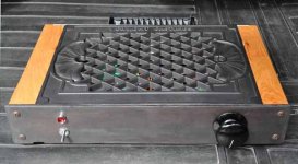
Finally finished my build of the My RefC. here are a few pictures.
Very pleased with the sound after quite a few hours listening.
Sounds much better with a nice looking volume knob (just kidding).
Thanks all.
Bill
Finally finished my build of the My RefC. here are a few pictures.
Very pleased with the sound after quite a few hours listening.
Sounds much better with a nice looking volume knob (just kidding).
Thanks all.
Bill
Attachments
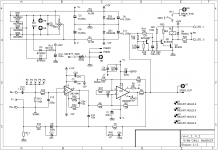
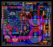
Here's my current shipping version (1.4.1, or simply 1.4) RevC schematic and layout, for easy reference.
The schematic is functionally equivalent to the original Mauro and Russ White Twisted Pear RevC Version.1.0 to 1.2 schematics, with a few minor differences:
1) C17, C18, C19, C20 found on Version 1.2 have been deleted.
2) C22 and C23 have been added - they're optional, to allow more flexibility in capacitor dimensions.
3) Various component values have been updated to conform more closely to the typical values in current use.
4) R37-C30 and R42-C32 have been swapped to facilitate more compact placement and routing on the PCB.
5) The (optional) CL60 isolator has been added.
6) P2 to P6 are additional drill holes for the input coupling capacitor C13.
7) Some nets/connectors have been renamed with more descriptive names: 0V is now SGND (Signal Ground), OUT is SPKR_OUT, and OGND is SPKR_RTN.
All the component designations from Version 1.2 have been retained exactly. The board sizes of Version 1.3 & 1.4 are identical, and both are larger than Version 1.2 (as mentioned in earlier postings). However, the location of IC2 may have shifted slightly on the layout from Version 1.3 to Version 1.4, so one may not be a drop-in replacement for the other - the heat-sink mounting location may differ slightly.
Attachments
Last edited:
On the last set I built I left one lead of the input coupling cap long so I could "short across" the cap if the owner wanted to DC couple the amp. Is it possible to add something like a pair of PCB header pins that you could put a jumper on to DC couple the amp?
EDIT: Once again I say bravo on the layout and HUGE bravo for leaving the silkscreen with the origins of the circuit.
EDIT: Once again I say bravo on the layout and HUGE bravo for leaving the silkscreen with the origins of the circuit.
Last edited:
On the last set I built I left one lead of the input coupling cap long so I could "short across" the cap if the owner wanted to DC couple the amp. Is it possible to add something like a pair of PCB header pins that you could put a jumper on to DC couple the amp?
OK - got it. Basically, a way to short the input cap with the cap in place, which is more convenient than desoldering and jumpering it. I'll put this in the to-do list for V1.5, which may take a while to happen.
OK - got it. Basically, a way to short the input cap with the cap in place, which is more convenient than desoldering and jumpering it. I'll put this in the to-do list for V1.5, which may take a while to happen.
Just a "nice to have" not anything at ALL important...
")
Brd looks great.
Lightspeed
Right on both counts Uriah, those are 35A rectifiers used as ground loop breakers as discussed here in this valuable and oft quoted article
Earthing (Grounding) Your Hi-Fi - Tricks and Techniques
Scroll down... for earth loop breaker circuit.
The lightspeed was offered at a discount during the group buy and the power supply with capacitance was discussed on the main thread by Regiregi (thanks Regi!) also he shows the ground loop breaker option and gives the link above.http://www.diyaudio.com/forums/group-buys/160768-myref_c-ultimate-bom-52.html#post2169865
One thing I couldn't get my head around, was whether or not I really needed one ground loop breaker per channel? I couldn't see the point of joining the ground of both channels before the ground loop breaker so I went for two breakers but I wish I understood this better...
I can cope with not understanding how the amp works, but the ground loop breakers have only three components and I can't work out how the hell they work.
About 100 hours listening to date and something is mellowing, but I couldn't honestly tell you if it is the amp or me that is mellowing out (most likely both).
I'll keep my eye's open for a more creative volume knob!
Cheers folks
Bill
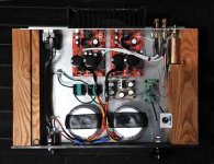
Looks to me like he has the lightspeed in there.
Are those two black squares with green rectangles.. are they rectifiers?
Uriah
Right on both counts Uriah, those are 35A rectifiers used as ground loop breakers as discussed here in this valuable and oft quoted article
Earthing (Grounding) Your Hi-Fi - Tricks and Techniques
Scroll down... for earth loop breaker circuit.
The lightspeed was offered at a discount during the group buy and the power supply with capacitance was discussed on the main thread by Regiregi (thanks Regi!) also he shows the ground loop breaker option and gives the link above.http://www.diyaudio.com/forums/group-buys/160768-myref_c-ultimate-bom-52.html#post2169865
One thing I couldn't get my head around, was whether or not I really needed one ground loop breaker per channel? I couldn't see the point of joining the ground of both channels before the ground loop breaker so I went for two breakers but I wish I understood this better...
I can cope with not understanding how the amp works, but the ground loop breakers have only three components and I can't work out how the hell they work.
About 100 hours listening to date and something is mellowing, but I couldn't honestly tell you if it is the amp or me that is mellowing out (most likely both).
I'll keep my eye's open for a more creative volume knob!
Cheers folks
Bill
Hey Folks,
I recentlycame across a clip from carver.com where Bob Carver (love/hate) describes both speaker wire gauge and placing a small resistor (1.5ohm) between the amp and speaker to make almost any amp sound more "tube-like". I am assuming he means warmer and more natural.
I am wondering if that type of modification is truly valid and if so, has it already been incorporated somewhere in the MyRef-C design. I am going to play around with both the "Britt Wire" he mentions (I have some super thin silver) and the resistor mod but welcome others opinions on his contention. If truely effective, I assume the resistor could be added internally in a Ref-C build.
For those who might be interested, the clip is located down the page at: CarverAudio.com - Welcome!
Regards, Bob M.
Hi Bob - if the 1.5R resistor is outside the outer voltage feedback loop, it should not make a significant difference to the sonics. It will decrease the DF, which may help for some kinds of speaker loads, but at the cost of reduced output power.
If it's inside the outer voltage feedback loop (which needs some mods/cuts to the PCB), it will definitely affect sonics - but the impact is hard to predict. YMMV, but I'm guessing that it may improve phase margin, decrease the output power, and increase the THD20 (distortion) by 6-12 dB.
If it's inside the outer voltage feedback loop (which needs some mods/cuts to the PCB), it will definitely affect sonics - but the impact is hard to predict. YMMV, but I'm guessing that it may improve phase margin, decrease the output power, and increase the THD20 (distortion) by 6-12 dB.
Carver Mod
Hey Siva,
My thought was not a mod to a PCB, just adding the resistor between the signal out and the speaker post inside the case. Not a big deal but I still own both a Carver M-1.0t power amp and a C-1 preamp from the 80s.What Bob Carver called "Sonic Hologram" in the C-1 is actually quite effective as a pre-5.1 "Stage Broadener". So I gave his suggestion some credibility. I am still vastly impressed by the Ref-Cs as is, but am always open to squeezing as much "Reality" out of them as possible. I hope others might also test the mod and report back.
Regards, Bob M
I recently acquired a pair of Dynaco A25s, and recapped them
with a Dayton 5.1uf film cap to replace the tired Jensen bipolar in
the tweeter network.
They sound simply awesome with the MyRef amp with absolutely no listening fatigue. I am a happy camper. Definitely a recommended
match.
with a Dayton 5.1uf film cap to replace the tired Jensen bipolar in
the tweeter network.
They sound simply awesome with the MyRef amp with absolutely no listening fatigue. I am a happy camper. Definitely a recommended
match.
Where do I find kits for MyRefC?
This one I found on eBay and it seems to be a MyRefC:
Classic lines LM3886 dual-channel +LM318 AMP/ DIY | eBay
Has someone tried it?
Carlos
This one I found on eBay and it seems to be a MyRefC:
Classic lines LM3886 dual-channel +LM318 AMP/ DIY | eBay
Has someone tried it?
Carlos
- Status
- This old topic is closed. If you want to reopen this topic, contact a moderator using the "Report Post" button.
- Home
- Amplifiers
- Chip Amps
- MyRefC build guide