It does seem a shame to take a simple tweak and turn it into a something so complex. I got lost after the table on values too!
Daniel, if I may be so bold, may I suggest a career in broadcasting? The TV news guys love somebody who can take a very simple incident and speak for hours about it while none of their viewers understand a word.")
Daniel, if I may be so bold, may I suggest a career in broadcasting? The TV news guys love somebody who can take a very simple incident and speak for hours about it while none of their viewers understand a word.
Eva said:A bare capacitor without series resistance can't tame an oscillation, it can only shift it to a lower frequency. Only series resistance introduces losses and damps ringing.
Yes! That's where I was going, but I don't know how to get there.
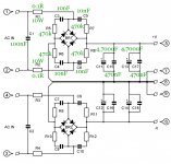
And, do you mean THIS: http://www.quasarelectronics.com/kit-files/smart-kit/1217.pdf (page 6)?
A different sort of photo here: http://www.quasarelectronics.com/kit-files/smart-kit/1218.pdf (bottom of page 7).
So that last one introduces both secondaries-side RC network and per-diode RC network for damping the oscilations. Makes sense to me, but the problem is the values. Now - for the AC secondaries, we've got a table of production-value caps, which is mostly fine, but then it'll be nice to put the series-resistance values in the table as well .
How does one determine the values on the diodes though, that is something that I can't figure out. Wouldn't it entirely depend onthe type of rectifier elements?
Oddly enough I do follow the posts allright so far. Thanks everyone for the input.
. How does one determine the values on the diodes though, that is something that I can't figure out. Wouldn't it entirely depend onthe type of rectifier elements?
Oddly enough I do follow the posts allright so far. Thanks everyone for the input.
AndrewT said:that Page6 schematic shows a proper supply.
Some well respected experts say that c1 & c2 should be around 10uF.
Who says keep them small?
But in essence, you need a calculation, based on your circuit, in this case related to the size of your secondary coil , and the frequencies you want to shift/dampen. While a "universal" value from a good reference is allright, being a little more precise is better, isn't it ?
AndrewT said:that Page6 schematic shows a proper supply.
Some well respected experts say that c1 & c2 should be around 10uF.
Who says keep them small?
c1 & c2 are on the primary (mains input) side.Atilla said:
But in essence, you need a calculation, based on your circuit, in this case related to the size of your secondary coil , and the frequencies you want to shift/dampen. While a "universal" value from a good reference is allright, being a little more precise is better, isn't it ?
Attachments
Atilla said:you need a calculation, based on your circuit, in this case related to the size of your secondary coil , and the frequencies you want to shift/dampen.
Your both absolutely right.audio1st said:Secondary surely?
I must have been half asleep. It's the dancing that does it (17hrs over the weekend and 6more on the last two nights).
I did some experimentation recently.
Using a small center tap transformer and a 1 piece bridge rectifier, applying the chart from post 23 http://www.diyaudio.com/forums/showthread.php?postid=1588619#post1588619 did make for a somewhat cooler heatsink. In my opinion, the easy little mod was worthwhile.
Next up, using 4 of the same cap for "ring around the rectifier" seemed to work in most cases, yet this was not as certain as when only one cap was used. Here's some results:
When the 4 cap deal worked out, then the heatsink would be half as warm. Also, when it worked, the diodes were simplistic "non-botique" models.
As a sort of measure, I had an FM radio tuned to a distant station during the above test. The signal meter went stronger when the rectifier was snubbed.
When it didn't work out (I don't have a scope), the effect was similar to defective diodes (that I have experienced). Although there weren't enough samples to say for sure, I'd assume that "ring around the rectifier" is possibly less-compatible with "soft switch" or "high performance" diodes like MUR, FR, etc. . . ., or at least the application didn't match up for me at the time I tried it.
In an effort to find a secondary side A/C cap that's easier to obtain than a wima, I found the epcos MKT caps. They are rated for high pulse strength, with the smaller lead spacing providing higher pulse strengths. I decided on B32529C8472J (4.7nF for my 300VA 18V+18V toroid). Unfortunately, it will be some time before I get a chance to test it, as I'm in the process of rebuilding a car amp before I build my BR100. I hope it will provide the heat reduction people are talking about, as that would be a big help with this amp.
Redshift187 said:In an effort to find a secondary side A/C cap that's easier to obtain than a wima, I found the epcos MKT caps. They are rated for high pulse strength, with the smaller lead spacing providing higher pulse strengths. I decided on B32529C8472J (4.7nF for my 300VA 18V+18V toroid). Unfortunately, it will be some time before I get a chance to test it, as I'm in the process of rebuilding a car amp before I build my BR100. I hope it will provide the heat reduction people are talking about, as that would be a big help with this amp.
I might be wrong but do not expect it to cause any heat reduction at all. Heat reduction typically comes with reducing the voltage or preventing oscillation if/when present. One *hack* that helps with this is putting a cap across the chipamp signal (inverting & non-inverting) inputs, maybe 220pF to 300pF.
In this post: http://www.diyaudio.com/forums/showthread.php?postid=1606736#post1606736
is a "way out" of capacitor differences--adding a resistor makes the internal variance more of a "moot point."
Question:
SO, I wonder if you can find the resistor value exactly like you'd do for a "woofer" in that you could measure the DCR and inductance for the transformer and, perhaps do this in the same way as you would calculate the zobel for a woofer? Maybe not? I don't know.
EDIT:
This is in reference to RC's in "ring around the rectifier" as seen in the photo of that post http://www.diyaudio.com/forums/showthread.php?postid=1606736#post1606736
Gopher said:Daniel
Ever since you started contributing to this forum I haven't understood a thing you've said. You're talking gibberish man.
If you use two of a capacitor in series, you get half values.
Okay so far?
Use two sets of that in parallel and you have the same value as a single.
There's a reason to use 4 instead of 1.
There are 4 diodes in your bridge rectifier.
For the textbook square shape of the bridge rectifier, adding 4 tiny capacitors (one per each diode) makes what appears to be "ring around the rectifier."
This will remove some efficiency from the diodes, but that which is removed is the most fragile--so you have removed a spike that causes rails to fluctuate. That, approximately 5%, spike is nearly useless for powering an audio amplifier. A useless input is a noise, so aren't you glad you removed it?
For LM3886, that's a 0.31C/W smaller size heatsink doing the same job when the amplifier isn't fed that noise.
More is possible--much more.
But what Eva says is entirely correct - if you want to smooth the oscilations completely you need a series resistance as well. In fact, the power supply schematic you posted as a reference has those: on both power rails and in the rectifier.
What I do wonder about the rectifier snubbers is how do you calculate the values? If I have a bridge of discrete diodes or a packaged rectifier bridge, what do I look for in the datasheet, prefferably, in order to calculate those?
What I do wonder about the rectifier snubbers is how do you calculate the values? If I have a bridge of discrete diodes or a packaged rectifier bridge, what do I look for in the datasheet, prefferably, in order to calculate those?
Atilla said:But what Eva says is entirely correct - if you want to smooth the oscilations completely you need a series resistance as well. In fact, the power supply schematic you posted as a reference has those: on both power rails and in the rectifier.
You may do either or both--just measure to assure functional benefit at end result.
What I do wonder about the rectifier snubbers is how do you calculate the values? If I have a bridge of discrete diodes or a packaged rectifier bridge, what do I look for in the datasheet, prefferably, in order to calculate those?
Information or measurements of your transformer's secondary.
What a shame that an interesting thread about what seems a straight forward, easy to implement mod became so complicated
Since I am a newbie and this mod means dealing with mains power, in order to play safe I would be grateful for some guidance as to the values of the capacitors before and after a dual (tween) secondaries 22X22 300VA transformer.
And another question, do I have to use X rated capacitors both before and after the transformer or only after?
Many thanks
Antonio
Nothing is ever as simple as it seems, is it I see no shame in this thread since it brought up detailed explanations and some practical measurements that show the results of it all.
Anyway - if you want to be straightforward - check the table on the first page. 2x22 for 300VA suggests 5.9nF per secondary and that's a commersially available value.
I've got the caps suggested by the article the OP reffered to but unless I missed it - they're not X1 caps, are they? At any rate - be sure to get a decent voltage rating for them.
I see no shame in this thread since it brought up detailed explanations and some practical measurements that show the results of it all. Anyway - if you want to be straightforward - check the table on the first page. 2x22 for 300VA suggests 5.9nF per secondary and that's a commersially available value.
I've got the caps suggested by the article the OP reffered to but unless I missed it - they're not X1 caps, are they? At any rate - be sure to get a decent voltage rating for them.
- Status
- This old topic is closed. If you want to reopen this topic, contact a moderator using the "Report Post" button.
- Home
- Amplifiers
- Chip Amps
- Tuning a PS Transformer on a GainClone.