I've worked out the correct parts for the caps between the trafo&rectifier, but I was wondering about the comments about the RC paralelled on the mains side.
What effect are we really looking to accomplish with this? I've seen this option offered at the mains side of the transformer windings in a couple of places, however without any details. I've also seen a lot of RCL filters installed at the mains, with R and C in parallel across the live and neutral and two L in series with both lines. Just as a reference - apparently a lot of PC's SMPS have that soldered directly at the mains socket. I haven't actually seen that being used anywhere else so far. For example, the one I found today, while scavenging some parts out of a scrapped PSU had a 0.33uF X2 cap in paralel to the PSU, a low-power resistor in paralel as well (gotta check the value, it was under the cap) and two inductors, wound around the two halves of the same circular core, in series with live and neutral.
I understand that a usual RC low-pass filter or an L low-pass filter would work, not passing those frequencies in the transformer in the first place, but I'm slightly confused about the one described in this thread and the inpult filter I'm talking about.
! said:Power supply manufacturers have been adding this cap for many years, or at least offering a spot for it on PCBs even if they omitted it to save a few cents.
The quality of the capacitor is not very important at all. Plain polyester film caps work fine.
I'd sure like a description, a sample, a documentation on how the AC side input filter works. Something applied would be best for me because of what could happen given my math skills along with the inappropriate combination of a presentation of a pagefull of equations. Photos, methods, and real examples would be great!
danielwritesbac said:
I'd sure like a description, a sample, a documentation on how the AC side input filter works. Something applied would be best for me because of what could happen given my math skills along with the inappropriate combination of a presentation of a pagefull of equations. Photos, methods, and real examples would be great!
It's application specific. We take it as a given that the AC line is noisey, but filtration depends on knowing if the powered equipment is susceptible and if so in what frequencies. Trying to come up with a generic equation including all variables including the particular transformer used is beyond my ability and possibly beyond practicality if there's a scope around to check the output or you're already running a simulator you can punch some numbers into.
! said:It's application specific. We take it as a given that the AC line is noisey, but filtration depends on knowing if the powered equipment is susceptible and if so in what frequencies.
Or if it is actually reliant on some noise as that tolerance was inbuilt into the design and needed for expected results of the component(s)?
Trying to come up with a generic equation including all variables including the particular transformer used is beyond my ability and possibly beyond practicality if there's a scope around to check the output or you're already running a simulator you can punch some numbers into.
Given a few examples, a correlation could be found, like what was done for this handy chart (earlier, same thread): http://www.diyaudio.com/forums/showthread.php?postid=1588619#post1588619 Is it fully accurate? No. But that's not possible given the wide variety of the components listed, so the chart is merely a "close estimate." With that sort of tool as a starting place (baseline), its a nicely shorter timeframe to successful application.
Another similar type of chart is here: http://www.partsexpress.com/resources/crossover-component-selection-guide.cfm And, while it doesn't result in exact values for every application, even so, its probable that the necessary value is reasonably similar to the one listed on the chart. Of course there are many exceptions; but, when the results quite literally speak for themselves (audio electronics), such a chart is a useful tool.
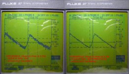
Scope shots, comparing transformer secondary capacitor effect:
- LM3886, BrianGT Boards
- XFM-D00012 Toroid (Dual 21.5vac @ 2.7A) (from ApexJR)
- 2 x 10,000uf @ 50vdc, Nippon Chemicon SMH per rail (total of 4)
- 2 x 100uf @ 100vdc, ELNA Cerafine, each amp
- shots taken at idle, no-load condition
XFM-D00012 Toroid (Dual 21.5vac @ 2.7A)
- 150nF @ 100v (yellow box film)
- across each secondary
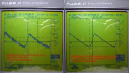
XFM-D00012 Toroid (Dual 21.5vac @ 2.7A)
- 2.2pF @ 250v RIFA PME271E X1 Series
- across each secondary
RIFA PME271E X1 Series Datasheet:
http://www.evoxrifa.com/cap_catalog/emisuppr/pme271e.pdf
- LM3886, BrianGT Boards
- XFM-D00012 Toroid (Dual 21.5vac @ 2.7A) (from ApexJR)
- 2 x 10,000uf @ 50vdc, Nippon Chemicon SMH per rail (total of 4)
- 2 x 100uf @ 100vdc, ELNA Cerafine, each amp
- shots taken at idle, no-load condition
XFM-D00012 Toroid (Dual 21.5vac @ 2.7A)
- 150nF @ 100v (yellow box film)
- across each secondary
XFM-D00012 Toroid (Dual 21.5vac @ 2.7A)
- 2.2pF @ 250v RIFA PME271E X1 Series
- across each secondary
RIFA PME271E X1 Series Datasheet:
http://www.evoxrifa.com/cap_catalog/emisuppr/pme271e.pdf
Attachments
bichi said:Scope shots, comparing transformer secondary capacitor effect:
- LM3886, BrianGT Boards
- XFM-D00012 Toroid (Dual 21.5vac @ 2.7A) (from ApexJR)
- 2 x 10,000uf @ 50vdc, Nippon Chemicon SMH per rail (total of 4)
- 2 x 100uf @ 100vdc, ELNA Cerafine, each amp
- shots taken at idle, no-load condition
XFM-D00012 Toroid (Dual 21.5vac @ 2.7A)
- 150nF @ 100v (yellow box film)
- across each secondary
XFM-D00012 Toroid (Dual 21.5vac @ 2.7A)
- 2.2pF @ 250v RIFA PME271E X1 Series
- across each secondary
RIFA PME271E X1 Series Datasheet:
http://www.evoxrifa.com/cap_catalog/emisuppr/pme271e.pdf
The AVX BF014E0154J is more likely to cause a pulse than to remove one. If you mapped it, it comes out to nearly ESR0 @ 10x less than its value, almost exactly like a blackgate or cerafine would do (if they existed in such a small size). So, at sizes larger than the recommended 1.5nF (see chart), you had a highly variable RC network, possibly down into the range of a 1.5uF cap--a lovely property of polyester if used on purpose. That model is a specialty product meant for bypassing large electrolytics in power supplies.
Hey, see if that yellow box cap has a T on top of it.
")
Maybe try a BC Vishay "370" series? Those are "normal" caps.
Howabout a nice old-fashioned 100v+ ceramic disc?--EDIT2: use a really cheap ceramic disc, not a "hi-k" or other specialty model.
EDIT:
THANK YOU!! Thanks for confirming that cap-too-big makes more noise. We had discussed this earlier. And some people think that 10nF is the only thing to snub the rectifier, then they buy a larger transformer. . . but, with this documentation, they can just buy a smaller cap. Wonderful!
danielwritesbac said:Hey, see if that yellow box cap has a T on top of it.
EDIT:
THANK YOU!! Thanks for confirming that cap-too-big makes more noise. We had discussed this earlier. And some people think that 10nF is the only thing to snub the rectifier, then they buy a larger transformer. . . but, with this documentation, they can just buy a smaller cap. Wonderful!
no, no "T" on top of "yellow box" 150nF film cap
- have no idea who manufacturer is...
- (parts usually from surplus or excess lab stock)
You are Welcome
- if you plan on using scope shots as reference, use corrected version, below
- have used small value capacitors on AC power supply transformers for years
- posted difference for educational purposes, so others can get an objective point of view.
Attachments
bichi said:
no, no "T" on top of "yellow box" 150nF film cap
- have no idea who manufacturer is...
- (parts usually from surplus or excess lab stock)
You are Welcome
- if you plan on using scope shots as reference, use corrected version, below
- have used small value capacitors on AC power supply transformers for years
- posted difference for educational purposes, so others can get an objective point of view.
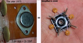
What about the common practice of "ring around the rectifier" like in this photo?:
EDIT: The original was on a 50vct (2x25) center tap of 300va.
Attachments
Originally posted by danielwritesbac THANK YOU!! Thanks for confirming that cap-too-big makes more noise. We had discussed this earlier. And some people think that 10nF is the only thing to snub the rectifier, then they buy a larger transformer. . . but, with this documentation, they can just buy a smaller cap. Wonderful!
This evidence does nothing to confirm a cap too big causes noise, quite the opposite it suggests that for every frequency of noise present the appropriate cap value has to be chosen to combat it. It's not as though we "must" choose only one capacitor if we're being picky about every last constituent of noise.
! said:This evidence does nothing to confirm a cap too big causes noise, quite the opposite it suggests that for every frequency of noise present the appropriate cap value has to be chosen to combat it. It's not as though we "must" choose only one capacitor if we're being picky about every last constituent of noise.
Of course you're entirely correct that just the right size is much better than either too much or not enough.
I'm just saying that the worst option is too much capacitance (too big). That was posted that for a "signpost" type guideline, because the component varieties of diode, cap, and transformer may make a "just right" size nearly impossible to discover unless one owns sophisticated measuring equipment.
I think its not so much about being picky on removing a small amount of power noise, but rather about little, inexpensive caps helping to match up diode+transformer choices and/or helping to decrease heat outputs. This is about money--purchasing many diodes and transformers to "luck" into the perfect combination and/or also buying large heatsinks. Or, we could find out what two little caps can do.
danielwritesbac said:
Of course you're entirely correct that just the right size is much better than either too much or not enough.
I'm just saying that the worst option is too much capacitance (too big). That was posted that for a "signpost" type guideline, because the component varieties of diode, cap, and transformer may make a "just right" size nearly impossible to discover unless one owns sophisticated measuring equipment.
I don't agree, that there is no such thing as too much capacitance except that too much is wasted money and space in the amp. Whether there is noise depends on the right capacitor for that filtering but unless there is problematic resonance added with paralleled caps they are practically always of benefit.
Some say lesser capacitance makes an amp more lively or something to that effect. That's quite possible, you're attenuating the bass if the power rails droop every time a bass note is played at sufficient volume (current) for it to matter, but the same is true with using an undersized transformer if you experiment with different sizes, or including a series inductor which also adds more power filtering. Often people say the smaller cap is better because they insist it has to only be big or little, as if it has to be only one cap per rail instead of having high capacitance for PSU then small fast caps for the amp board plus generous further decoupling. An infinite amount of capacitance will make the amp the most tonally accurate but that doesn't necessarily mean anyone has to feel that is what sounds the best to them, a synergy with the source and speakers counts too.
I think its not so much about being picky on removing a small amount of power noise, but rather about little, inexpensive caps helping to match up diode+transformer choices and/or helping to decrease heat outputs. This is about money--purchasing many diodes and transformers to "luck" into the perfect combination and/or also buying large heatsinks. Or, we could find out what two little caps can do.
Heat output should not change, unless there was prior oscillation that adding the caps prevented.
! said:I don't agree, that there is no such thing as too much capacitance except that too much is wasted money and space in the amp. . . .
In this case, the caps for this particular application are on the AC side of the rectifier. If you perform too much rectification with capacitance, then the diodes won't work as expected.
http://en.wikipedia.org/wiki/Rectifiers
What?danielwritesbac said:If you perform too much rectification with capacitance, then the diodes won't work as expected.
http://en.wikipedia.org/wiki/Rectifiers
Which extract from Wiki do you want us to read?
AndrewT said:What?
Which extract from Wiki do you want us to read?
The beginning of this section explains the usage of a large capacitor across the AC side, wheras the end of this section explains the usage of a large capacitor across the DC side. http://en.wikipedia.org/wiki/Rectifiers#Electrolytic
Obviously, the AC waveform must be reasonably intact in order to work as described in this section: http://en.wikipedia.org/wiki/Rectifiers#Full-wave_rectification because if it had already been smoothed out ("mashed flat" into DC) via overlarge caps on the AC side, then the expected event of an AC signal entering a diode in your rectifier would have been unavailable due to lack of signal.
Therefore the general view of capacitance being "the more the merrier" isn't a good idea when snubbing the rectifier (on the AC side), because it could unintentionally result in rectifier technology that is 91 years out of date.
More might be merrier on the DC side of the rectifier, but that idea isn't true of the AC side of the rectifier.
The scans posted earlier show that nicely.danielwritesbac said:
In this case, the caps for this particular application are on the AC side of the rectifier. If you perform too much rectification with capacitance, then the diodes won't work as expected.
http://en.wikipedia.org/wiki/Rectifiers
Yes, somehow I lost track of the discussion (had another browser window open) and wasn't talking about the same caps.
Oh yes, but it makes the opportunity to relate it to "a useful signal."
Since all of the active pins of a chipamp are potentially an input path, we're taking an opportunity to restrain the power input to useful signal. This task is also performed on the input pin via a tiny value capacitive load (RF blocker), and this task is performed on the output pin via the output zobel (because the + speaker wire is a huge antenna connected straight into your negative feedback loop, NFB).
If any of these noise blocking caps are overlarge in value, they could cause harm to a useful signal or its harmonics.
Another way to relate "snubbing the rectifier" is because there's a tiny capacitor directly across the secondaries of the transformer. This is quite similar to the early Pioneer B20 projects that had a Piezo tweeter (which IS a capacitor directly across the coil of the B20). In that application, any similar size capacitor could have reduced the peak of the B20 and it wasn't necessary for the capacitor to output sound--a sound that some of the projects aimed rearwards at a wall or upwards at the ceiling. My point is that the small cap across the B20's coil was not a crossover effective within the audio band (that capacitor size didn't harm the useful signal), but yet, it was a capacitor, and, as such, did remove some of the effects of inductance.
For reference, that was 130nF (0.13uF) according to this: http://www.piezosource.com/general/datasheets/Piezo_1001_1005A.pdf document. That is probably also the maximum size to consider for use in a speaker output zobel. In my opinion, its quite inappropriate to use the same maximum size all the time, when too-large is too-easy (component variety and more accidents waiting to happen) along with documented adverse effects. That also includes roasting the resistor. Why not go smaller on the speaker output zobel cap too? The application is quite similar to the one in this thread. Surely we could generate a chart for that too?
Since all of the active pins of a chipamp are potentially an input path, we're taking an opportunity to restrain the power input to useful signal. This task is also performed on the input pin via a tiny value capacitive load (RF blocker), and this task is performed on the output pin via the output zobel (because the + speaker wire is a huge antenna connected straight into your negative feedback loop, NFB).
If any of these noise blocking caps are overlarge in value, they could cause harm to a useful signal or its harmonics.
Another way to relate "snubbing the rectifier" is because there's a tiny capacitor directly across the secondaries of the transformer. This is quite similar to the early Pioneer B20 projects that had a Piezo tweeter (which IS a capacitor directly across the coil of the B20). In that application, any similar size capacitor could have reduced the peak of the B20 and it wasn't necessary for the capacitor to output sound--a sound that some of the projects aimed rearwards at a wall or upwards at the ceiling.
My point is that the small cap across the B20's coil was not a crossover effective within the audio band (that capacitor size didn't harm the useful signal), but yet, it was a capacitor, and, as such, did remove some of the effects of inductance.For reference, that was 130nF (0.13uF) according to this: http://www.piezosource.com/general/datasheets/Piezo_1001_1005A.pdf document. That is probably also the maximum size to consider for use in a speaker output zobel. In my opinion, its quite inappropriate to use the same maximum size all the time, when too-large is too-easy (component variety and more accidents waiting to happen) along with documented adverse effects. That also includes roasting the resistor.
Why not go smaller on the speaker output zobel cap too? The application is quite similar to the one in this thread. Surely we could generate a chart for that too?- Status
- This old topic is closed. If you want to reopen this topic, contact a moderator using the "Report Post" button.
- Home
- Amplifiers
- Chip Amps
- Tuning a PS Transformer on a GainClone.