Thanks Atilla,
I had found that value (5.9nf) in the chart but I wanted to be sure I was right.
And what about the ones before the trafo as mentioned by AndrewT. Is it the same value? I did not find a chart or the way to calculate these ones.
Yes the suggested WIMA FKP 1 are not X rated but they are high voltage-
http://www.maplin.co.uk/Module.aspx?ModuleNo=98162&DOY=18m9 - and from what I understood from the thread only the ones before the transformer have to be X rated.
Regards
Antonio
This is a fascinating thread that I missed earlier. I have two questions:
Is the capacitance of the capacitor across the secondary the same no matter what the voltage and current are as long as the VA is the same? So for example, is the capacitance of the capacitor the same for a 1A, 25V transformer as for a 0.1A, 250V transformer?
Does the size of the capacitor depend only on the VA rating of the transformer and not on the amount of current it is providing?
Dave
Hi Dave!
This transformer, suitable for an economical LM3886, LM3875, TDA7294 build, is a 48v center tap, which is 24vac, 0v, 24vac. Transformer Example
48volts x 3ampers = 144VA
(48 * 3) = 144
In this thread, you can find a "cheat sheet" chart and spreadsheet where you can look up the estimated capacitor sizes to use.
For a couple more equipment examples, here's a bridge rectifier for center tap transformer (wheras the 0v is provided by the transformer's 0v Center Tap cable); and, here's bridge rectifiers for a dual secondaries transformer (for dual secondaries transformer use two bridge rectifiers +-, 0v,+- stacked like a pair of flashlight batteries wheras the centerpoint is the 0v).
In Mark Houston's Synergy chip amp project, see Photograph 04: Star Ground and Snubbed Rectifier.
Although the capacitance value is the same as using just 1 cap per transformer winding, Mark Houston's implementation is more thorough with 1 cap per each diode (which is four per each of the bridge rectifier units in the above post--see the photo), and it is frequently seen in radio receivers. The informal nickname for it is "ring around the rectifier."
He has used small polyester capacitors, and these have a high ESR (internal resistance) and so a computer simulation would need to use equivalent RC networks (snubbers) in order to represent that circuit.
In this thread, there is some discussion of capacitor types having a different effect on sound, and surely a classic ceramic (acting like "just a cap" because of almost no ESR) would make a different effect than a small polyester cap (which may act like an RC).
Of course you can use either type of capacitor, but there's my guess on why the various different types would make for a different effect.
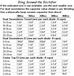
Here's a handy smaller chart for it (attached).
*And, if you get unwanted audio effects, its probably because the capacitance size is too large. Expected results are "less shout" in direct proportion to "less dynamics" and a cooler heatsink temperature (as measured by temp probe).
Although the capacitance value is the same as using just 1 cap per transformer winding, Mark Houston's implementation is more thorough with 1 cap per each diode (which is four per each of the bridge rectifier units in the above post--see the photo), and it is frequently seen in radio receivers. The informal nickname for it is "ring around the rectifier."
He has used small polyester capacitors, and these have a high ESR (internal resistance) and so a computer simulation would need to use equivalent RC networks (snubbers) in order to represent that circuit.
In this thread, there is some discussion of capacitor types having a different effect on sound, and surely a classic ceramic (acting like "just a cap" because of almost no ESR) would make a different effect than a small polyester cap (which may act like an RC).
Of course you can use either type of capacitor, but there's my guess on why the various different types would make for a different effect.
Here's a handy smaller chart for it (attached).
*And, if you get unwanted audio effects, its probably because the capacitance size is too large. Expected results are "less shout" in direct proportion to "less dynamics" and a cooler heatsink temperature (as measured by temp probe).
Attachments
Summary of my understanding.
I had little to no problem following the thread and found it very educational as well as a valuable primer for my own psu build for the pearl-two phono preamp.. An amp that greatly benefits from the quietest unregulated supply reasonably concievable by an unequiped and untrained diyer like me.
It seems straight forward and rather basic, and jargon may serve to make it seem more complicated, and certainly there is alot of detail amd a measure of approximation, but its not complex as a basic overview of the effects of capacitance in this specific application. Snubbing line noise on mains/primaries has different requirements than snubbing secondaries before the rectifier, again there are different requirements to filtering after the rectifiers. I will be placing a small x type across my switch contacts to prevent arching pops when switching and snubbing the secondaries. Line rated X types are needed on the primaries, but x types are not necessary on the secondaries - only ratings of sufficient values for the application, plus a little headroom to avoid failures.
From reading Ive gathered that Snubbing effectively alters the noise band, and when used with low values of series resistance, softens/attenuates the diode ringing noise as a RC type filter tuned to the rectifier. The tables provided represent typical, not exact, values for a variety of transformers used, but ultimately the exact values needed to optimice filtering requires indepth analysis of both the transformer and the specific diodes, and then trial and error. As this thread was started to give us diyers an approximation, the value of the guidance is appreciated, as is the explanations about the table's limits. After the rectifyer we use much larger crc capacitance to ac nas sort of shock absorbers to level out the dc ripple.
Am i on track so far?
With that said, the table specifies estimated values for use with either ei or torroidal type transformers. Im using a chinese sourced unshielded dual-25v p-core split bobbin type transformer to reduced noise coupling between primary and secondary windings.
With a p-core, which table of values would i be best served with, ei values or torroidal values? Or might a pcore need different values all together? I would guess a pcore has more in common with ei types but would like some thoughts.
For those competent and trained with the maths, im using 25 + 25 split bobbin 50va 1a p-core. Im assuming then 1.1nf or 820pf across each secondary, prior to the rectifiers.
I've seen a word of mouth recomendation to use .22 (uF?) snubbers as per the original designers recommendations. Thoughts on that? Its a huge value discrepancy from the suggested values here. The pearl likely draws less than 100mA of dynamic load..
Last edited:
Daniel
Ever since you started contributing to this forum I haven't understood a thing you've said. You're talking gibberish man.
")
Let's find out?
If you've got just one full wave bridge rectifier (like KBPC2504), then the snubbing is easy. We'd just get a 2u2 polyester cap (preferably ac rated "X" cap) and a 50R trimmer (use for variable resistor) to create an adjustable RC. This RC goes across the bridge rectifier from ac to ac ("~" to "~" markings), which is the transformer secondary's hookup. Then, usage looks like simply turn the dial for best results and then lastly, measure the trimmer in ohms and replace with a 1w resistor of same value.
If you've got just one full wave bridge rectifier (like KBPC2504), then the snubbing is easy. We'd just get a 2u2 polyester cap (preferably ac rated "X" cap) and a 50R trimmer (use for variable resistor) to create an adjustable RC. This RC goes across the bridge rectifier from ac to ac ("~" to "~" markings), which is the transformer secondary's hookup. Then, usage looks like simply turn the dial for best results and then lastly, measure the trimmer in ohms and replace with a 1w resistor of same value.
placement of the capacitor
Konstantine in his original post said that it would be best to place the capacitor that is between the transformer and the rectifiers closest to the transformer as opposed to the rectifier. Does anyone know the reason for this? Has anyone done any experiments with the two placements?
Konstantine in his original post said that it would be best to place the capacitor that is between the transformer and the rectifiers closest to the transformer as opposed to the rectifier. Does anyone know the reason for this? Has anyone done any experiments with the two placements?
The transformer secondary outputs are connected directly to the bridge rectifier inputs.
Putting the capacitor across the transformer outputs is exactly the same as putting the capacitor across the bridge rectifier inputs.
BUT!!!!!
You need a snubber here, NOT a lonely capacitor !!!!!!
Putting the capacitor across the transformer outputs is exactly the same as putting the capacitor across the bridge rectifier inputs.
BUT!!!!!
You need a snubber here, NOT a lonely capacitor !!!!!!
Hi guys.
I read all that thread but I found nothing for my case.
I use a 300va 25+25v but secondaries are parallel to give 35V 12Amp.
If I read table on post 22 http://www.diyaudio.com/forums/chip-amps/128278-tuning-ps-transformer-gainclone-3.html#post1588611
Can I conclude I must use a 12nf capacitor like on 300va 25-0-25?
Best regards.
Julien
Konstantine in his original post said that it would be best to place the capacitor that is between the transformer and the rectifiers closest to the transformer as opposed to the rectifier. Does anyone know the reason for this? Has anyone done any experiments with the two placements?
That placement is maximal for effectiveness, but you'd also need to know the (see capacitor datasheet) internal equivalent resistance for your specific model of cap.
You'd have a shortfall of resistance if that cap wasn't either a ceramic disc or dip-polyester (blob, not box). That means, for the other sorts of caps, you'd have to add a resistor to make an RC (you can be sure of it--don't overspend on filter caps!).
It isn't the least bit different from a woofer's voice coil in that you'd need to target relevant frequencies with an RC to soak/heat up excesses.
As far as placement goes, I have identified ideal (as far as audio) locations for power filters, and those two are either between transformer and rectifier (had you meant to filter ac), or at the edge of the amplifier board (had you meant to filter dc).
As close to the relevant noise (unwanted signal) as possible, is sure to get you epic respect and effectiveness with filters. That's the thing to do!
Other locales, as in irrelevant locales, for filters just make it harder to do, take a lot longer, much less effective, and we just don't have time for that.
Konstantine's suggestion of situating the RC directly upon the inductor looks logical; because, maximizing the effectiveness of a filter requires positioning it as close as possible to the need of it.
- Status
- This old topic is closed. If you want to reopen this topic, contact a moderator using the "Report Post" button.
- Home
- Amplifiers
- Chip Amps
- Tuning a PS Transformer on a GainClone.