

PIC Microcontroller as a potential DSP / DDS Element
Posted 3rd November 2013 at 03:29 AM by googlyone
Updated 3rd November 2013 at 03:31 AM by googlyone
Updated 3rd November 2013 at 03:31 AM by googlyone
I noted that the new PIC32 series micro controllers include I2S along with the SPI interface. Well at least a few in the range do. This got me to thinking:
- A 32 bit micro using a fairly efficient RISC architecture
- With I2S in and out
- That runs at 80MHz.
I chose the PIC32MX450F256H.
Surely to god I can do something fun with this. But what?
Ultimately I will try chucking some IIR filters in here to see how they go (there is heaps of processing time available). But in the first instance I want to do a DDS. Reason being that I have more active crossovers than I have speakers (and that is saying something! - ask my long suffering wife!).
One thing that I have been on the look out for is a decent DDS synthesister for audio band that has really low distortion. My current Audio synthesiser uses the AD9952 DDS chip. OK, this runs at 400MHz, but it does use a 14bit DAC, and can be run right down into the Hz regime. Overkill? Hell yhea. Does it work? Surprisingly well really.
I did have to put switching to allow the AD9952 to drive an opamp output rather than through an RF balanced to single ended transformer, but it works.
That said, if I can build a software DDS in the PIC, then I can drive one of the many CS4398 DACS I have laying around. This should give me audio bandwidth DDS - with the associated "no bounce" and nice control that software provides, with distortion way down below -100dBc.
I have done back of the envelope (read in my head) sums on th operations required to do the DDS, and it will be a shoo in for the PIC32.
So where am I at?
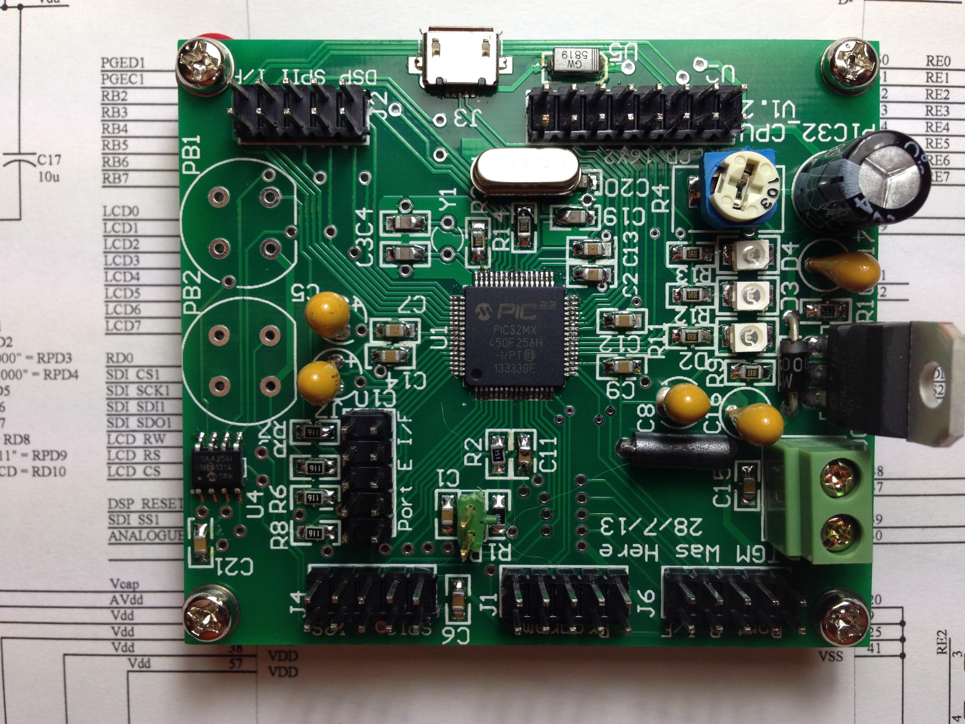
I looked around (briefly) for a development system with the PIC32 and good DAC, or interface. Nothing jumped out and smacked me in the face. But then I was probably too busy laying out a PCB....
The design of this board was driven by a couple of things:
- I wanted to be able to drive the I2S / SPI allowing me to play with audio DSP and the DDS idea.
- This meant I wanted audio in and out on I2S
- I also wanted this board to be backward compatible with the older PIC designs I use, as it would allow me to reuse the code base I have, and aso provide me a simple set to work environment - i.e. existing hardware to test it on.
What did I include then? Not an awful lot really, as this is a generic controller:
- SPI (by two)
- Input from 5VDC to to power the board and a regulator for the PIC (3.3V)
- 16X2 character LCD interface and contrast control
- A couple of pushbuttons just in case I want to do a simple implementation, and to assist in Set to Work
- A couple of LEDs to again, assist with set to work and simple applications
- The USB interface wired bu and a microAB USB connector (that I have not payed with yet)
- Pretty much every spare I/O pin wired to headers.
Where am I at?
I have ported the old 8 bit PIC code from the 18F4520 to the PIC32. This was a mix of "really easy" and "deeply embarrassing".
The easy bit was that once I have implemented all the initialisation ans set up for the PIC32, things like I/O and the SPI worked a treat.
The embarrassing bit was that the old 8 bit code harks back to a design that used a PIC16F877. That deign was so memory constrained (both program and RAM) that I was forced to do some truly ugly things with variable usage and function calls to save bytes.
First: I had to unravel a heap of this stuff, some of which I still don't have the stomach to do - including a couple of the key data structures being defined as globally accessible variables.
Secondly: I felt utterly obliged to define all the processor specific stuff in the header file. It was a pretty big job, but now it is done, I am much more relaxed about porting the code again. It was a good lesson in "What makes sense in the heat of the moment can be REALLY STUPID in the long term."
Getting this right in the first place would probably have made life easier right there and then, but since I kind of started the development with "Make a LED flash" and grew it from there, some good practise got missed on day one.
Thirdly: Moving from an 8 bit to 32 bit processor does imply changes to some data types. Notably the length of an INT. Should it be a problem? Not if I wrote the code for the original application considering the general case of data types.
But I was saving the last byte remember... so being a hardware engineer I did some - well lets just say expedient - things
So I had to spend a couple of days trawling through code ensuring that I am now being rather more thoughtful in what pointers are pointing at, and masking the bits I want to use and those I don't!
So what next?
- I have the main code for my crossover up and running. This includes a HMI, EEPROM read and write stuff, interrupts and timers.
- I will next strip this all back as the basis of an audio synthesiser.
- I will start with Sine, square and triangle (though I think square is better done analogue externally)
- I want to use two channels and allow timing pulse generation on the second channel.
- Then pulse (burst) sweeps, AM, FM and multitone.
The one thing I really do want to look into (now I have started!!!!) is the timing mechanisms available in the PIC32MX, and what these mean for jitter.
I am pretty sure I will be OK here, but do need to do some experiments.
- A 32 bit micro using a fairly efficient RISC architecture
- With I2S in and out
- That runs at 80MHz.
I chose the PIC32MX450F256H.
Surely to god I can do something fun with this. But what?
Ultimately I will try chucking some IIR filters in here to see how they go (there is heaps of processing time available). But in the first instance I want to do a DDS. Reason being that I have more active crossovers than I have speakers (and that is saying something! - ask my long suffering wife!).
One thing that I have been on the look out for is a decent DDS synthesister for audio band that has really low distortion. My current Audio synthesiser uses the AD9952 DDS chip. OK, this runs at 400MHz, but it does use a 14bit DAC, and can be run right down into the Hz regime. Overkill? Hell yhea. Does it work? Surprisingly well really.
I did have to put switching to allow the AD9952 to drive an opamp output rather than through an RF balanced to single ended transformer, but it works.
That said, if I can build a software DDS in the PIC, then I can drive one of the many CS4398 DACS I have laying around. This should give me audio bandwidth DDS - with the associated "no bounce" and nice control that software provides, with distortion way down below -100dBc.
I have done back of the envelope (read in my head) sums on th operations required to do the DDS, and it will be a shoo in for the PIC32.
So where am I at?
I looked around (briefly) for a development system with the PIC32 and good DAC, or interface. Nothing jumped out and smacked me in the face. But then I was probably too busy laying out a PCB....
The design of this board was driven by a couple of things:
- I wanted to be able to drive the I2S / SPI allowing me to play with audio DSP and the DDS idea.
- This meant I wanted audio in and out on I2S
- I also wanted this board to be backward compatible with the older PIC designs I use, as it would allow me to reuse the code base I have, and aso provide me a simple set to work environment - i.e. existing hardware to test it on.
What did I include then? Not an awful lot really, as this is a generic controller:
- SPI (by two)
- Input from 5VDC to to power the board and a regulator for the PIC (3.3V)
- 16X2 character LCD interface and contrast control
- A couple of pushbuttons just in case I want to do a simple implementation, and to assist in Set to Work
- A couple of LEDs to again, assist with set to work and simple applications
- The USB interface wired bu and a microAB USB connector (that I have not payed with yet)
- Pretty much every spare I/O pin wired to headers.
Where am I at?
I have ported the old 8 bit PIC code from the 18F4520 to the PIC32. This was a mix of "really easy" and "deeply embarrassing".
The easy bit was that once I have implemented all the initialisation ans set up for the PIC32, things like I/O and the SPI worked a treat.
The embarrassing bit was that the old 8 bit code harks back to a design that used a PIC16F877. That deign was so memory constrained (both program and RAM) that I was forced to do some truly ugly things with variable usage and function calls to save bytes.
First: I had to unravel a heap of this stuff, some of which I still don't have the stomach to do - including a couple of the key data structures being defined as globally accessible variables.
Secondly: I felt utterly obliged to define all the processor specific stuff in the header file. It was a pretty big job, but now it is done, I am much more relaxed about porting the code again. It was a good lesson in "What makes sense in the heat of the moment can be REALLY STUPID in the long term."
Getting this right in the first place would probably have made life easier right there and then, but since I kind of started the development with "Make a LED flash" and grew it from there, some good practise got missed on day one.
Thirdly: Moving from an 8 bit to 32 bit processor does imply changes to some data types. Notably the length of an INT. Should it be a problem? Not if I wrote the code for the original application considering the general case of data types.
But I was saving the last byte remember... so being a hardware engineer I did some - well lets just say expedient - things
So I had to spend a couple of days trawling through code ensuring that I am now being rather more thoughtful in what pointers are pointing at, and masking the bits I want to use and those I don't!
So what next?
- I have the main code for my crossover up and running. This includes a HMI, EEPROM read and write stuff, interrupts and timers.
- I will next strip this all back as the basis of an audio synthesiser.
- I will start with Sine, square and triangle (though I think square is better done analogue externally)
- I want to use two channels and allow timing pulse generation on the second channel.
- Then pulse (burst) sweeps, AM, FM and multitone.
The one thing I really do want to look into (now I have started!!!!) is the timing mechanisms available in the PIC32MX, and what these mean for jitter.
I am pretty sure I will be OK here, but do need to do some experiments.
Total Comments 2
Comments
-

 I did a software DDS back in the 80's using a 10MHz 68000. I'm not so sure its totally compatible with your chosen DAC though for the simple reason that a DDS does not generate evenly spaced clock pulses - it has some inherent jitter. Not sure how the CS4398 will like being given that kind of clock but hey there's nothing like trying it to see.
For myself I'd be more inclined to try it out with a normal multibit type DAC such as the TDA1387. Even better than that, a DAC which takes in a sample pulse to transfer the numbers to the output, like PCM1702.Posted 6th November 2013 at 05:31 AM by abraxalito

-
I hear wha you are saying WRT timing jitter. This is exactly the reason why the PIC32MX450F256H caught my attention. It has hardware and interrupts that allow some cunning tricks to avoid exactly what you describe.
I am approaching this by using the PIC32MX I2S interface as the master. This allows the PIC to generate the LRCLK, BCLK and data clock. It does this with inbuilt hardware timers that are independent of software.
The reason I am approaching it this way is that I should get a very stable timing clock for the DAC.
So how do I generate the DDS data? The DDS code will be in an Interrupt Service Routing that is called each time the I2S starts sending a pair of L/R data words to the DAC.
The nett result of this is intended to be:
- The LRCLK timing is generated by a hardware derived clock from the crystal oscillator.
- This is completely independent from the software execution
- The DDS software knows the timing at which the DAC will get the data it generates - as this is driven by the LRCLK which is hardware driven
- I can use an interrupt flag from the I2S hardware interface to call an ISR and load the next DDS data into the I2S buffer
Things this needs:
- A microcontroller with a hardware I2S interface with hardware clock divider for LRCLK and MCLK. Thus the choice of PIC32MX450 - two of these built in
- Code in the ISR that is efficient enough to get its stuff done in one word period on the I2S interface (20uS odd).
- Interrupts set up OK - not a big deal
- Me generating code that works
My real question is how stable the PIC32 clock is, and what jitter there is on the LR and MCLK in particular. From my cursory read I am expecting these to be well behaved.
Hitter on the ISR timing is obviously not relevant, provided it loads data into the I2S buffer in a timely manner.
I have had enough time to think through the code. It is actually quite simple really. At least on paper! I need to find the time to code it up and see.Posted 7th November 2013 at 10:46 AM by googlyone

