Would the LME49713 current feedback opamp work in the first stage?
It might, yes. Though it needs a DIP-SOIC adapter and possibly some ceramic bypass caps.
Hi Rjm and other manufacturers of Phonoclone 3,
i have a problem with my Phonoclone 3, it picks up radio signals.
The boards have been purchased by RJM, already full of components, so I just put the boards in the chassis and connected to the RCA, while the power supply is the same as my VSPS.
Can you help to reduce radio interference?
Regards
i have a problem with my Phonoclone 3, it picks up radio signals.
The boards have been purchased by RJM, already full of components, so I just put the boards in the chassis and connected to the RCA, while the power supply is the same as my VSPS.
Can you help to reduce radio interference?
Regards
330 pF capacitor between the inverting and noninverting pins of the input op-amp should reduce the interference. You can solder the capacitor to the underside of the board, to pin 2 and 3 of IC1.
Also be sure to use shielded cable for the phono interconnects.
The OPA27 op amp is susceptible to RF pickup, and careful shielding will be needed when the phonoclone is used in places where RF interference is especially strong.
Also be sure to use shielded cable for the phono interconnects.
The OPA27 op amp is susceptible to RF pickup, and careful shielding will be needed when the phonoclone is used in places where RF interference is especially strong.
Construction questions
I'm starting to case up the power supply and VSPS 300i boards and I had a few questions.
In the power supply, I'd rather not have to drill through the bottom of the enclosure for a bolt to mount the transformer. How are you all mounting the transformer?
The power supply just has a transformer, fuse, switch, and rectifiers. I noticed in a search that the rectifiers can be mounted directly to the case since the package has a through hole. I guess I expected to mount the rectifiers and fuse holder on a small board though. If the rectifiers are attached to the case, is there a good way to do that, again, without drilling through the box?
I think the same question comes up with attaching the boards too. I have the standoffs mentioned in the construction thread and I was looking for ways to mount them to the box without putting holes in the box.
I'd appreciate any ideas, thanks all.
Here's an nice example of a typical build. Yes, rectifiers and toroid are bolted to the chassis; that's the normal way to do it. In principle diodes and transformer could be bolted to a board, and the board slid into the chassis if your chassis has rails to allow this..
Attachments
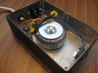
Here's an nice example of a typical build. Yes, rectifiers and toroid are bolted to the chassis; that's the normal way to do it. In principle diodes and transformer could be bolted to a board, and the board slid into the chassis if your chassis has rails to allow this..
One other question -- is that a special T connector for the common outputs from the rectifiers? If so, can you point me to where I could get those?
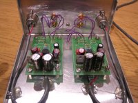
The boards are normally secured to the chassis with standoffs, 5-8 mm in length, and M3 screws. I dug another photo out of my PC that show this.
The photo is not a power supply I built, but looking at the photo the "T" connection is almost certainly soldered wires covered with yellow electrical tape.
The photo is not a power supply I built, but looking at the photo the "T" connection is almost certainly soldered wires covered with yellow electrical tape.
Attachments
Burson Op Amps
I've been asked several times now about whether Burson Op Ampsand similar modules can be substituted into the VSPS and Phonoclone circuits.
The answer is no.
And it's not because they rub me the wrong way by writing "op amp" as one word, either. It's because they don't present the necessary documentation for me to make a judgement.
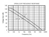
Check out the image below, taken from the OPA27 datasheet. The NE5532 used in the VSPS kit will have roughly similar data. The open loop voltage gain is seen to be over 100 dB at 10 Hz, falling to 40 dB at 100 kHz in the case of the OPA27. The OPA37, being uncompensated, has even more open loop gain.
An OPA27 in a Phonoclone typically runs at 30 dB closed loop gain. In order to maintain that gain, the open loop gain of the op amp must be significantly above 30 dB over the entire audio frequency range, to 20 kHz at least.
Does the Burson op amp have a high enough open loop gain? Since they don't supply any such data, we have no way of knowing. As it appears to be designed for DAC I-V stages, line stages, and headphone amplifiers, it's a good bet to assume the open loop gain is very low compared to a general purpose IC.
iifc a different manufacturer of a similar module claimed 12 dB open loop gain, and it would not surprise me to learn the Burson circuit is of a similar magnitude.
I've been asked several times now about whether Burson Op Ampsand similar modules can be substituted into the VSPS and Phonoclone circuits.
The answer is no.
And it's not because they rub me the wrong way by writing "op amp" as one word, either. It's because they don't present the necessary documentation for me to make a judgement.
Check out the image below, taken from the OPA27 datasheet. The NE5532 used in the VSPS kit will have roughly similar data. The open loop voltage gain is seen to be over 100 dB at 10 Hz, falling to 40 dB at 100 kHz in the case of the OPA27. The OPA37, being uncompensated, has even more open loop gain.
An OPA27 in a Phonoclone typically runs at 30 dB closed loop gain. In order to maintain that gain, the open loop gain of the op amp must be significantly above 30 dB over the entire audio frequency range, to 20 kHz at least.
Does the Burson op amp have a high enough open loop gain? Since they don't supply any such data, we have no way of knowing. As it appears to be designed for DAC I-V stages, line stages, and headphone amplifiers, it's a good bet to assume the open loop gain is very low compared to a general purpose IC.
iifc a different manufacturer of a similar module claimed 12 dB open loop gain, and it would not surprise me to learn the Burson circuit is of a similar magnitude.
Attachments
Lost one channel yesterday...
The only funny thing that happened was the power went out at the house yesterday while everything was on. Before that both channels worked without issue.
I switched all the inputs around and ruled out the TT and the pre & power amp.
I did notice that the "LM"s did have different values at the drain source and gate - I am presuming that they should be the same - just opposite polarity?
The only other possibility would be the op-amp itself. I have a couple more duals kicking around but I would rather rule out the regulators first.
What are the proper values for each regulator at each pin?
General comment: a power cut isn't a big deal. It's the power coming back on that's the problem. If the power goes off, the first thing to do is switch off then unplug the audio system. Commercial audio equipment usually has overvoltage protection, but the VSPS does not.
Take out the dead op amp (it's dead...). Measure the voltage at the op amp socket pin 4 to COM and pin 8 to COM. Should be -10 and +10 V respectively [edit: or whatever the vregs you are using are set to], within 100 mV. Since one channel is working, it would seem the power supply is fine as it is shared for both channels.
If you get 10V just go ahead and replace the op amp.
Surge protection is your friend...
Gotcha...I studied a little further and understand now why pins 1, 2, and 3 respectively are different for the LM's since 1 and 2 are flipped essentially.
I will check the voltages and hopefully just swap in another opamp. I have a few different varieties kicking around.
Thanks!
I will check the voltages and hopefully just swap in another opamp. I have a few different varieties kicking around.
Thanks!
I have built my VSPS last week, i've checked continuity on signal paths..OK. Plugged in..Nothing..Nada..Niente..
Recheck..i have continuity on "-" signal route..but not on "+" signal path...can someon can help me with "point checks"'?
Plese forgive my terrific English..
Grazie,
Gianni
Recheck..i have continuity on "-" signal route..but not on "+" signal path...can someon can help me with "point checks"'?
Plese forgive my terrific English..
An externally hosted image should be here but it was not working when we last tested it.
Grazie,
Gianni
Hi,
i am a little bit confused regarding R7.
With your VSPS Kit you attached a very nice overview and schematic (doc. ver. 1.6). Here R7 and R7L is 68K.
Here:
RJM Audio - The Very Simple Phono Stage
..R7 is 33K
What is wrong, what is right?
KR Barossi
i am a little bit confused regarding R7.
With your VSPS Kit you attached a very nice overview and schematic (doc. ver. 1.6). Here R7 and R7L is 68K.
Here:
RJM Audio - The Very Simple Phono Stage
..R7 is 33K
What is wrong, what is right?
KR Barossi
- Home
- Source & Line
- Analogue Source
- The Phonoclone and VSPS PCB Help Desk