is the only difference on the new rev 35b boards additional holes for the mica caps? i purchased one of the phonoclone 3 kits and just assembled it today. i had to stretch the leads of the mica caps to fit. anyhow, i was looking at your site and noticed the new board revision. that is the only difference the jumped out at me. is there anything else?
Ongoing hum saga...
Ive had an unresolved hum/RF problem is my Phonoclone that was bypassed by shelving it and using a VSPS and Cinemag combo. I recently started troubleshooting it again and was able to eliminate the RF with 300pf caps across the inputs of the first IC. I then decided to try a battery supply to see if isolating the PC from the AC line would help. The hum vanished! So Ive now checked all the connections on the PS and Pclone cases and all seems fine. Im using a single bridge rectifier and I dont have the XLR power plug isolated from the case. Seems the PS diagram has changed since my build. I constructed the original version that is shown below. Might the revised layout help?
amt
Attachments
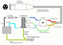
... I constructed the original version that is shown below. Might the revised layout help?
Hi,
interesting, I also reduced a lot the RF/hum by the caps at the inputs of the IC and I also built the old fashioned power supply with single rectifier and a very low rf noise is still there.
Renato
The main change in the new phonoclone boards (35b) is the addition of a dedicated GND pad, which is a special tap of "COM" that connects directly to the turntable ground and chassis. This seemed like a more sensible, foolproof way of doing it than getting people to connect COM to the chassis at the XLR jack, and makes the Phonoclone consistent with the current VSPS boards.
It's too early to tell whether the new boards have solved the RF/hum problem some of you persistently have trouble with. No such complaints so far. The changes were not intended to fix the problem however ... it was just to make things more intuitive and coherent.
The changes to the power supply are in the same vein. Using two bridge rectifiers is unlikely to reduce the hum, the main reason for making it the "official" recommendation is that this scheme is far, far harder to mess up.
What will make a phonoclone gone wrong right again? No simple answer, as far as I know.
- For 60 Hz stuff, keep the power supply in a separate chassis, or well away from the input wires if in the same chassis. Use metal chassis, and rigorously shield all input and output wires.
- For RF, the 300pF cap across the input opamp input terminals seems to do the trick for most people.
- Batteries of course eliminate the 120 Hz problem, as there is no ripple voltage to get into the inputs... but I as a solution it is rather extreme.
One thing worth trying if you haven't already is drastically reducing the gain by lowering R2 to something like 330 ohms.
Lowering R2 does the trick for some people, doesn't help for others.
It's worth noting that the VSPS has 100% field success, despite a very similar layout and the same basic connection scheme. It seems that once the circuit gain goes over a certain threshold - different for different systems - all manner of problems break out. The VSPS never gets close to that threshold, the Phonoclone occasionally crosses it.
The construction guide is current as of this writing.
Attachments
Last edited:
Hi RJM...I've just put a Third Tube on your 6DJ8 Phono Amp to make it a Stand Alone...I ran your Output Caps into (2) 100K Pots and 1K Grid Stoppers into the same Design as your Output Stage...But one of the 1uf Input Caps went bad, so I swapped both out with .3uF's that I had, and now it works Great...I've seen Designs using from .1uF to 4uF for Output/ Input Caps...How do they Effect the Sound, and what do You think is Best for a (3) Tube 6DJ8 Phono Amp?
@sled108
The smaller it is, the less bass response. The bigger it is, the worse it sounds, the bigger is becomes, and the more it costs.
Oversimplification but you get the idea.
Take 40, divide by the load impedance in kiloohms, the number is the required capacitance in microfarads.
For a 100k volume control, the coupling capacitor should be 40/100 or 0.4 (0.47uF).
For the outputs to drive an amplifier with 25k input impedance, the coupling capacitor should be 40/25 or 1.6 (2 uF).
Note that a single 6DJ8 is not the world's greatest preamp as the output impedance is rather high. Fine as long as the cables are not that long, and the amplifier impedance is above 25k.
External PSU and amp case connection
Hello,
I have been working on two projects: VSPS and opamp-based headphone amplifier. For VSPS everything is clear thanks for this post and RJM website, but when I started to search the forum for more information about noise and proper grounding I have found this thread: http://www.diyaudio.com/forums/chip-amps/115698-understanding-star-grounding.html
The thread also refers to Rod Elliott website article: Earthing (Grounding) Your Hi-Fi - Tricks and Techniques.
My question is about one detail which cought my attention: the way how ground connection is made in ESP schematic and not used in RJM PSU connection (please disregard ground loop braker shown in ESP site. My question is not about it).
Let's talk about VSPS PSU: RJM Audio - Construction Guide
In the first drawing of the PSU, the earth connection from the IEC socket goes directly to the case (there is also a note to connect transformer's shield if exists). So, this is the same for both threads. Now, what is different is secondary side of the transformer. In RJM site the green common wire, COM, goes directly with V+ and V- out to the amp case. There, I guess, all signal grounds are connected together, and with added COM connection are connected to the amp's case.
The detail, which is different from VSPS PSU is connection of common wire, COM, on the secondary side of the transformer to the case in ESP PSU.
Sorry, if that question was already asked, but the thread grow up to really big one and I was not able to find an answer. Are both approaches correct in reference to different project than VSPS? As I have mentioned at the beginning I want to build headphone amplifier based on OPA134 chips with external PSU. Like VSPS, I want to put voltage regulators by each chip. Since I am a beginner I am not sure which option to use and not to have problems with hum.
My worry is also about safety. If PSU and amp's cases are not linked together, like in VSPS, will fuse be triggered if something happens in amplifier case?
Thank you for the help !!!!!
The grounding scheme of the VSPS etc. will work equally well for a headphone amplifier. Try it and see. There is no risk of electrical shock as the output voltages are isolated and low.
High voltages, the story changes. I'd use a loop breaker as described by ESP for all but the amplifier, which can be earthed directly.
High voltages, the story changes. I'd use a loop breaker as described by ESP for all but the amplifier, which can be earthed directly.
- Home
- Source & Line
- Analogue Source
- The Phonoclone and VSPS PCB Help Desk