@topdog
Voltage is always "with respect to" a given reference point. If you have 12 V and -12 V at the opamp power pins with respect to ground then all is well. The regulators should have about +16 V and -16 V with respect to ground at the input pin and +12 and -12 V with respect to ground at the output pin. Ground, common, IN- and OUT- should all be connected and therefore at 0 V with respect to ground.
It is a common mistake to connect one of the regulators backwards or incorrectly.
@quan
I still use Black Gate N for C3, as my build dates back to the time they were still available. Your transformer etc are all fine, no need to worry about tweaking or changing anything, though you can experiment with C3 is you feel you have to.
Appreciate your patience with me. Still learning here. I'm good with the basics, but have never done anything with a split supply so this is new territory for me.@topdog
Voltage is always "with respect to" a given reference point. If you have 12 V and -12 V at the opamp power pins with respect to ground then all is well. The regulators should have about +16 V and -16 V with respect to ground at the input pin and +12 and -12 V with respect to ground at the output pin. Ground, common, IN- and OUT- should all be connected and therefore at 0 V with respect to ground.
It is a common mistake to connect one of the regulators backwards or incorrectly.
And you hit it on the head with the regulator. Bonehead of the month here. Used the same pinout for the negative reg as for the positive one, which is obviously a big mistake. Although the literature says the reg is "practically indestructable", I think I managed to damage it. It's reading -15v with respect to ground at the output pin. Going to do a complete teardown and rebuild it from scratch as soon as Mouser gets the new one here (today hopefully).
Hi Richard, thanks for the tip- regarding the max value of C3-does it affect the performance if higher value cap is used? -I see some Valab PIO 10uF/100V for 6USD each or 4.7uF for 3USD. Currently it runs on the Arcotronics 2uF MKP.
Thanks.
PS-can't find BG ANYWHERE-PC-NO STOCK., AURICAP?
Thanks.
PS-can't find BG ANYWHERE-PC-NO STOCK., AURICAP?
Hi there,
I have just finished building my VSPS project
and am quiet happy with the sound quality except for
a background hum that is more noticable at higher volume
any help would be most appreciated.
Thanks
Success Soldered a new pair of heavily shielded RCA cables into my turntable now no noticable hum unless i crank the volume to earth shattering
(but then the music masks it anyway
Finished the rebuild last night. Works perfectly and sounds great! So much better than the built-in in my Kenwood. Just need to finish fabricating the chassis and it'll be done.
Question - I used the NE5532P per the parts list. It's my understanding that OPA2604 is a direct replacement for the NE5532. Is that correct? If so, will it make an appreciable difference? Reason I ask is I have one sitting here, but don't want to swap it out if it'll do any damage.
Question - I used the NE5532P per the parts list. It's my understanding that OPA2604 is a direct replacement for the NE5532. Is that correct? If so, will it make an appreciable difference? Reason I ask is I have one sitting here, but don't want to swap it out if it'll do any damage.
@quan
BG are discontinued, and the N 4.7uF/50 disappeared from stores years ago.
2uF is generally sufficient, increasing the value tends to make the bass a bit boomier, the treble softer. It's a matter of taste to some extent.
@topdog
You can switch in the OPA2602 and see if you like it, there is no risk of damage. Any 8 pin dual audio opamp can be substituted, and many more besides.
Thanks again for everything Richard. Swapped in the OPA. Can't tell much, if any difference, but will probably compare again once the break-in period is done.
Another question for you - I need to build another one of these, but am looking at the VSPS 300 instead. It's not readily apparent from reading your site -- do I need a separate power supply for each channel or can I just run two sets of leads from the xreg board? My first thought is this would be that it's okay, but your write-up hints at separate supplies.
Another question for you - I need to build another one of these, but am looking at the VSPS 300 instead. It's not readily apparent from reading your site -- do I need a separate power supply for each channel or can I just run two sets of leads from the xreg board? My first thought is this would be that it's okay, but your write-up hints at separate supplies.
HI RicHARD, JUST TEST RUN THE PHONOCLONE 3-HUM+++,
have tried dummy load input with 47R-hum level unchange.Have reground using input ground instead of COM making no difference
I have not try 330pF on IC1 input as yet.
I had VSPS300 working fantastic without any noise.
Please advise what should i try next?
have tried dummy load input with 47R-hum level unchange.Have reground using input ground instead of COM making no difference
I have not try 330pF on IC1 input as yet.
I had VSPS300 working fantastic without any noise.
Please advise what should i try next?
Hi Rjm,
I purchased these boards (http://www.diyaudio.com/forums/group-buys/142708-phonoclone-vsps-group-buys-9.html), already assembled, what are the two holes on pins 2 and 3 of IC1 (C0)?
I have the problem of radio signals and i want to solder the capacitor to pin 2 and 3 of IC1.
I soldered the capacitor underside of the boards or in two holes near IC1?
Regards
Hi Richard
catridge- Denon DL103
R2- was 1.5K now adjusted to 1k-make no difference to level of hum.
interconnect was shielded, and power V+/V-/COM-twisted and away from signal lines.
Have change ground arrangement using inputs ground making no difference.
I have no rf issues just hum
Funnily enough- using dummy load , if only left channel is used then no hum -dead mouse quiet??, but as soon as right channel dummy-loaded then hum occur.
Quan.
@Dario1997 ... good. One support ticket down and one to go.
@quan ... you are afflicted by this odd ground loop issue I've seen a couple of times but not experienced personally. It's peculiar characteristic is that both channels need to be powered and connected for the hum to happen.
Without knowing the cause, I had hoped that the dedicated GND pad of the rev. 35b boards would solve the problem. It's been a long while since I've had any reports of the issue. Which board revision are your working from?
Final question, is your power supply dual mono or a shared transformer?
/R
Last edited:
.........
Funnily enough- using dummy load , if only left channel is used then no hum -dead mouse quiet??, but as soon as right channel dummy-loaded then hum occur.......
Quan.
Sounds like a ground loop in the signal leads.
I typically tie both channel signal grounds together inside at the entrance of the enclosure, use a single signal ground in the enclosure.

Thanks quan for the extra info.
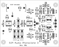
Found your order details. You have the older version of the boards, 32e, from Aug 2009. The current layout 35b is attached. Notice the position of the new GND pad just behind the IN- and OUT- connections.
Thanks by the way for using dummy loads for testing as it takes the input cable/cartridge/tonearm wiring out of the equation and makes it at lot easier for me to try and figure out what's going on.
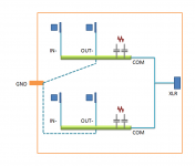
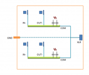
You've connected the chassis to the inputs, and that didn't work, and you've connected the chassis through COM and that didn't work. Since you are using a shared power supply COM L and R connect together ... while this is not usually a problem it is a liability that must be kept in mind. The shared COM is, in a nutshell, why tying the IN- together and grounding them as Troy suggests doesn't work.
I would like you to try one last thing before I roll up my sleeves on this: basically rewire the ground to mimic the new GND connection by splitting the OUT- signal into two wires from the board, one wire goes to the insulated output RCA shield, the other to the ground lug. COM for each channel connects as before, doubling up at the XLR jack, and IN- connect to insulated RCA jacks.
Let me know if it makes any difference at all.
Found your order details. You have the older version of the boards, 32e, from Aug 2009. The current layout 35b is attached. Notice the position of the new GND pad just behind the IN- and OUT- connections.
Thanks by the way for using dummy loads for testing as it takes the input cable/cartridge/tonearm wiring out of the equation and makes it at lot easier for me to try and figure out what's going on.
You've connected the chassis to the inputs, and that didn't work, and you've connected the chassis through COM and that didn't work. Since you are using a shared power supply COM L and R connect together ... while this is not usually a problem it is a liability that must be kept in mind. The shared COM is, in a nutshell, why tying the IN- together and grounding them as Troy suggests doesn't work.
I would like you to try one last thing before I roll up my sleeves on this: basically rewire the ground to mimic the new GND connection by splitting the OUT- signal into two wires from the board, one wire goes to the insulated output RCA shield, the other to the ground lug. COM for each channel connects as before, doubling up at the XLR jack, and IN- connect to insulated RCA jacks.
Let me know if it makes any difference at all.
Attachments
Last edited:
- Home
- Source & Line
- Analogue Source
- The Phonoclone and VSPS PCB Help Desk