They appear to be pin compatible with the LM317/337, so: yes.
*****
I was thinking again about parts count, regulation, and adding RC filter stages after the voltage regulator to attenuate high frequency noise.
If it worked it would be a cheap and simple way to improve the power supply. My gut feeling is that perhaps as it stands presently the design overly favors low impedance at the expense of increased noise. An RC filter network would redress that in a simple tradeoff of increased low-frequency output impedance for decreased high frequency noise levels. How much needs to be applied is an open question.
If someone wants to try it, put an RC filter consisting of 22 ohms and 100 uF at the power terminals of the input opamp and see if it makes a positive difference. Since very little noise is contributed from the second stage the benefit of applying the filter to the output stage is less obvious. An RCRC networks with the output opamp tapped from after the first RC and the input opamp powered from after the second RC stage is another option to consider if the initial trials are promising.
/rjm
rjm said:They appear to be pin compatible with the LM317/337, so: yes.
*****
I was thinking again about parts count, regulation, and adding RC filter stages after the voltage regulator to attenuate high frequency noise.
If it worked it would be a cheap and simple way to improve the power supply. My gut feeling is that perhaps as it stands presently the design overly favors low impedance at the expense of increased noise. An RC filter network would redress that in a simple tradeoff of increased low-frequency output impedance for decreased high frequency noise levels. How much needs to be applied is an open question.
If someone wants to try it, put an RC filter consisting of 22 ohms and 100 uF at the power terminals of the input opamp and see if it makes a positive difference. Since very little noise is contributed from the second stage the benefit of applying the filter to the output stage is less obvious. An RCRC networks with the output opamp tapped from after the first RC and the input opamp powered from after the second RC stage is another option to consider if the initial trials are promising.
/rjm
That is a good thing. I would put that as near the op amp as possible and add the largest non-electrolytic cap you can fit to bypass the electrolytic to take care of higher frequency noise. As always, good ground wiring to a common point, avoiding loops, is advised.
Starting building the Phonoclone myself I have some starter questions, I hope someone can comment.
If I want to build the Phonoclose as generic as possible (allowing for a great number of MC carts that is), what should I do? Is it sufficient to solder R1 (input loading) and R2 (gain) on sockets or should I also socket other parts?
Another question (forgive me if it's too newbie), where in the circuit can I change the Input Termination Capacitance? Isn't that something you need with a MC pre?
Last thing. I have a Denon DL-103 but also an AT MM cart. If I want to have both MM and MC support, should I also build a VSPS next to the Phonoclone for the MM cart?
Thank you,
Ralph
You can build a VSPS and Phonoclone in separate boxes, with a single external power supply that you plug into whichever unit you want to use. If you insist on the convenience of a MM/MC switch, its far easier to use a single conventional circuit with switchable loads and gains.
The Phonoclone isn't a jack-of-all-trades phono stage. Its MC only, and its not guarenteed to work with every MC cart out there.
If you want to keep the Phonoclone as versatile as possible, set R1 to zero, and either socket R2 or make it switchable over a range of values from 150 to 1500 ohms. (150, 330, 680 1500 suggested). Socket the input opamp so that you can use a OP27 or move to OP37 for really high gains)
There is no input load, so no input capacitance to worry about setting.
/R
Hi folks,
I am totally new in this forum, and the reason why I joined is the phonoclone. My only experience in DIYHiFi is speakerbuilding for about 25 years, therefore I`m a little bit afraid if the skills aren`t to high for me. After only using digital equipment for some years, I am in the mood to reactivate my old analog gear to get some new kicks. I did not want to use my AV-amp with my old TD 125, SME 3009 and DL 103 so I got me an used integrated tube amp with line inputs only. I still have an old Ortofon MCA-76 step up, which sounded good to me on nearly any Integrated amp with a good MM-phonostage together with the DL 103. But since then nearly 30 years have passed and I doubt if it`s still ok in comparism to newer equipment.
There are two ways for me:
1. build a phonoclone, and leave the MCA-76 in the attic,
2. build a VSPS and use it with the MCA-76
any recommendations?
I nearly don`t know anything about active electronics, OP`s, transistors and so on. Until now my knowledge ends with L, C and R in passive crossovers. It would be very nice if you could tell me the "state of (phonclone)art" equipment-list for the use with the standard DL 103.
I think of using a 50 VA 2x12V torodial transformer for each channel, together housed in an diecast enclosure for a 3,5"USB harddrive. For the 2 phonostages I`d use a similar housing.
What Do you think about my plans?
After reading the complete postings here, but not remembering all of them ( and understanding max. half of them) I got the impression that this is a very constructive and helpful desk and allways on topic. The support from rjm seems to be 1.st class.
In other communities a thread couldn`t be as long as here without drifting anywhere.
Thanks for your help in advance.
bruderse

")
I am totally new in this forum, and the reason why I joined is the phonoclone. My only experience in DIYHiFi is speakerbuilding for about 25 years, therefore I`m a little bit afraid if the skills aren`t to high for me. After only using digital equipment for some years, I am in the mood to reactivate my old analog gear to get some new kicks. I did not want to use my AV-amp with my old TD 125, SME 3009 and DL 103 so I got me an used integrated tube amp with line inputs only. I still have an old Ortofon MCA-76 step up, which sounded good to me on nearly any Integrated amp with a good MM-phonostage together with the DL 103. But since then nearly 30 years have passed and I doubt if it`s still ok in comparism to newer equipment.
There are two ways for me:
1. build a phonoclone, and leave the MCA-76 in the attic,
2. build a VSPS and use it with the MCA-76
any recommendations?
I nearly don`t know anything about active electronics, OP`s, transistors and so on. Until now my knowledge ends with L, C and R in passive crossovers. It would be very nice if you could tell me the "state of (phonclone)art" equipment-list for the use with the standard DL 103.
I think of using a 50 VA 2x12V torodial transformer for each channel, together housed in an diecast enclosure for a 3,5"USB harddrive. For the 2 phonostages I`d use a similar housing.
What Do you think about my plans?
After reading the complete postings here, but not remembering all of them ( and understanding max. half of them) I got the impression that this is a very constructive and helpful desk and allways on topic. The support from rjm seems to be 1.st class.
In other communities a thread couldn`t be as long as here without drifting anywhere.
Thanks for your help in advance.
bruderse
Since you have a DL103 already and express no particular plans to use MM cartridges, the Phonoclone would seem to me to be the better option.
- grab the .brd files from the homepage, and place an order with Olimex for a set of Phonoclone boards.
- compile a parts list and order what you need.
I suggest just going ahead with it and not worry too much about which brand of capacitor is currently considered to be the best one to use, etc.
If you have any questions though feel free to email or pm me.
/Richard
Hi Richard,
I would like to order PCBs from Olimex for VSPS but am nervous that the re-order # RM270606 applies both to VSPS AND PhonoClone... is this correct? Any possible chance of confusion and getting the wrong parts? I realise that the order info includes a description as well as the # RM270606, but I just need some reassurance here...
many thanks.
I can confirm that's correct. There is usually multiple items on each order number, but Olimex files the phototools for all the items together under that number. It references both boards in this case, so you have to specify which and how many.
The order number doesnt tell them what your order will be, it just helps them find the previously filed datasets you are duplicating.
/R
P.S. Let us know how you make out with Olimex.
The order number doesnt tell them what your order will be, it just helps them find the previously filed datasets you are duplicating.
/R
P.S. Let us know how you make out with Olimex.
P.S. Let us know how you make out with Olimex.
I ordered the board a couple of weeks ago. Communication and shipment was without hassle. The only thing that they really have to work out is the taxes (in the EU). Bulgaria is a EU member since Jan 1st so they have to charge taxes for the other EU members. Obviously that wasn't stated on their website. I got my boards as samples therefor.
PS: I got the re-order discount
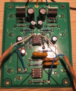
Just finished my Phonoclone on the workbench. Before I hook them up to my turntable and amplifier for testing, are there things to measure (i.e. testpoints) to indicate if I made some mistakes? If the tests are OK, I will put them in nice metal enclosures.
BTW: the holes for C1 and C2 were too small for my mica caps. Assembling the other parts went smoothly.
Ralph
BTW: the holes for C1 and C2 were too small for my mica caps. Assembling the other parts went smoothly.
Ralph
Attachments
Bursen op-amps and Phonoclone?
It seems like a good idea.
Any comments?
They are not cheap but would one think they must be good.
Could there be any conflicts in the first stage? Second stage being rather typical, does not seem to matter.
Thanks for any comment and advice.
It seems like a good idea.
Any comments?
They are not cheap but would one think they must be good.
Could there be any conflicts in the first stage? Second stage being rather typical, does not seem to matter.
Thanks for any comment and advice.
Ralph said:Before I hook them up to my turntable and amplifier for testing, are there things to measure (i.e. testpoints) to indicate if I made some mistakes?
Ralph
You should by all means check for input offset voltage. It should be 0.0mV or very close. Should you have something like 0.6Volts, don't connect a cartridge. It may (and probably will) fry.
Rüdiger
BTW: the holes for C1 and C2 were too small for my mica caps.
Yeah sorry about that. My mica caps didn't fit either. I had to drill out the through holes a little.
With the circuit board there is less worry about making the wrong connections, but with one probe connected to COM, test the voltages at the opamp power pins and IN+. You should see the regulated voltage at the power pins, and zero at IN+.
rjm
Re: Bursen op-amps and Phonoclone?
Hi,
I am not sure that a "discrete opamp" will make a better sound. It will make the sound different, that's sure.
The most of the sound of any simple-minimalist circuit design depends strongly on the PSU, and in particular by the impedence matching between the PSU and the circuit fed. The psu has it's own impedence, this is a huge point, and this is often sadly forgotten.
I think these blessed guys here have optimized this design for using an LM317-337 type regs with a minimalist psu. So I would not invest all that money to buy somenthing better on the paper that could result in a failure in sound.
Two years ago a friend of mine, a top engineer working in professional audio industry, built an MM phonostage with OP-amps. On the paper the design was top sounding, but the reality was a bit different. The sound was terrible.
Some months later he changed the high specs toroidal trafo, with an expensive C-Core by Bartolini (Italy). Bartolini is one of the best producer trafos for the tube comunity. The result was that the sound changed from night-to-day, and I can say that that phono stage is one of the best MM stage I have ever heard.
So before to struggle with "top-esoteric-high-specs" components at the end of the signal, we should concentrate where the signal starts up to its end.
Bye for now
J. Cukkurullo
QUOTE]Originally posted by rickmcinnis
It seems like a good idea.
Any comments?
They are not cheap but would one think they must be good.
Could there be any conflicts in the first stage? Second stage being rather typical, does not seem to matter.
Thanks for any comment and advice. [/QUOTE]
Regulators experiments
Hi Guys,
I built prototype of the MM stage before to go for the MC. Richard thanks for this design, it's a bargain for the monney, GOD bless you.
For the moment I am using a R-core trafo (12V/100VA per rail)
First of all I used mil-specs 30uF/30V tantalum caps on the adj pin of the LT317 reg, this makes a big difference. More detail, dynamics and overall musicality. I guess (not sure) some better noise rejection as well.
Than, mantaining the the tantalum on that position I compared the LM317 vs the LT1086, LT1085 regs. It's funny but the LT1085 (3A) sounded the best. With the LT1085 the stage is much bigger, and gained fluidity in mids and higs, while transient response is on a new level.
Impedence and load regulation behaviour of the different regs is important here.
I also tried an IBM laptop psu, you won't believe that, but despite the noise which was somehow loud, the musicality was excellent considering the price of the psu ($7 on ebay)!
I would be delighted to get feedback from all of you.
Bye for now
J. Cukkurullo
cukkurullo,
When you stated
were you referring to mechanical noise or induced signal noise?
Could you describe?
When you stated
,IBM laptop psu, you won't believe that, but despite the noise which was somehow loud
were you referring to mechanical noise or induced signal noise?
Could you describe?
Ed Lafontaine said:cukkurullo,
When you stated
,
were you referring to mechanical noise or induced signal noise?
Could you describe?
I mean electrical noise. A lot of analougue guys are concearned with noise, but if they are they should change their technology, vinyl produces a lot of noise... but who cares when the SNR is acceptable and the noise is not mdoulated with the frequency!!!!!
Cukkurullo
I think these blessed guys here have optimized this design for using an LM317-337 type regs with a minimalist psu. So I would not invest all that money to buy somenthing better on the paper that could result in a failure in sound.
For he record, no, I did not optimize the phono design for a particular power supply.
Its open-ended in this regard, though I have repeatedly stressed the importance of a high quality power transformer and the minimum amount of filter capacitance.
Power supply design is more trial and error than exact science. Once things get down to the level of which type/value of capacitor to use on the Vreg ADJ pin, your guess is as good as mine. On paper there is no additional advantage putting more than 10uF here, but the impedance characteristics and dielectric losses of different capacitors will surely change the sound slightly.
As I worte earlier, a far more dramatic change would be to experiment with RC stages on the Vreg output.
/R
rjm said:
...
Its open-ended in this regard, though I have repeatedly stressed the importance of a high quality power transformer and the minimum amount of filter capacitance.
... your guess is as good as mine.
/R
Richard I did not want to say that I was discovering somenthing special. I just wanted to report some findings.
Cukkurullo
- Home
- Source & Line
- Analogue Source
- The Phonoclone and VSPS PCB Help Desk