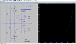
The S-Reg originally had capacitors C3,C4 which essentially lowered the output impedance (and the output ripple) by increasing the feedback.
These capacitors are removed in all the currently shipping boards. The original S-Reg board had them though, as did the CrystalFET.
The output impedance with the caps connected is about 1-2 ohms. Without, it's about 20-25 ohms.
If anyone is interested in the experiment, it is a simple matter to connect a 10-100 uF capacitor across the 10 k resistors (R9,10 in the schematic below, shown as 11.5k) and see if you hear any improvement or loss.
Btw the capacitors were removed for the following reasons,
1. Additional ripple rejection was not needed.
2. Additional feedback did not sit well with me as something you want to connect to an opamp which is already loaded up to the gills with negative feedback.
3. The capacitance could stress the transistors Q7,8 on start up by putting a large voltage across the base-emitter terminals.
4. It seemed to make no difference either way and I needed the board real estate.
Attachments
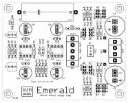
The user must NEVER break the Safety connection between Protective Earth (PE) and the chassis.Take another look at my emerald photo. The red toggle switch at the back makes or defeats the connection mains earth to ground.
The user must NEVER break the Safety connection between Protective Earth (PE) and the chassis.
You'd have trouble at my house. I have no Protective Earth. 2 wire only! So no safety to break.

But yeah, as I said above, any metal chassis you put mains voltage into should be earthed if possible to bring in into regulation.
My PS is compliant with the European norm for a double insulated device. A PE - chassis connection is therefore not required and is not desirable ( possible earth loop problems if connected). The only reason I included a ground to earth connection switch is because I renovate unearthed vintage turnables which could, if defect, present a shock hazard. i.e. for my own protection.The user must NEVER break the Safety connection between Protective Earth (PE) and the chassis.
Regards, Dutch Keith
I agree! I made a mistake here for sure. Funny thing is I didn't do this before or since. I must have been distracted!Jose is right: you've actually connected the chassis to the circuit common multiple times on each board, once through the GND pad and once through the COM pad. These are already connected internally so only one of these needs to connect to the chassis. Normally that's the GND of each board, but it doesn't matter you could use COM if you want. I don't recommend both but I doubt it makes much difference.
Google wasn't as helpful as I hoped.
The problem is most of the discussion is on appliances which run on mains voltage like a hair dryer or a toaster, rather than transformer isolated electronics.
As far as I can tall though a power transformer in a box would be considered Class 0 is it was disconnected from earth and the box was metal, Class I if it was connected to earth, and Class II if it was disconnected from earth but in a plastic box.
Class 0 is considered bad and prohibited in the UK/EU where many countries run at 220 or 230 VAC, but is relatively common in countries with 100-120 V mains.
The case work does not have to be made of plastic. My PVR has metal casework but no mains earth.
An externally hosted image should be here but it was not working when we last tested it.
Double insulated or class 2 electrical appliances are products that have been designed in a way so as not to require a safety connection to electrical earth (These products must NOT have a safety connection to Earth).
These products are required to prevent any failure from resulting in dangerous voltage levels becoming exposed causing a shock etc. This must be done without the aid of an earthed metal casing. Ways of achieving this include double layers of insulating material or reinforced insulation protecting any live parts of the fitting.
There are also strict requirements relating to the maximum insulation resistance and leakage to any functional earth or signal connections of such appliances. Products of this type are required to be labelled "Class II", "double insulated" or bear the double insulation symbol (the symbol displayed above)
ClassII devices must be DESIGNED to be safe in the absence of the PE wire.What are physical distinctions of a double insulated device?
Isn't the only insulation between the mains wires and the chassis the plastic on the wires?
This then requires the design to be manufactured and tested and guaranteed to be safe.
That's it in a nutshell Mr. Onion!
The Class II requirement for the mains current bearing circuit for a transformer based PS can be summarized thus
The mains carrying leads and IEC socket connector pins are doubly insulated and the primary winding of the transformer is isolated from the chassis (and secondary windings!) by at least 2 layers of insulation.
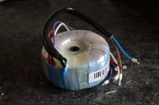
Toroidal transformers provide typically 4 levels of insulation between the primary and secondary windings and between primary winding and chassis
1. the insulation coating of the primary winding wire
2. the insulation wrap of the primary winding
3. the insulation wrap of the secondary windings
4. the insulation coating of the secondary winding wire
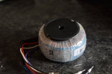
The ones I use have an additional insulation level with respect to the chassis in that the transformer is mounted on a plastic foot with the space between the plastic fixation column and outer insulation wrap being filled with some sort of non conducting resin.
It's always a good idea to use a good quality transformer with sturdy insulation wraps. Not only for safety reasons but they sound better too!
The Class II requirement for the mains current bearing circuit for a transformer based PS can be summarized thus
The mains carrying leads and IEC socket connector pins are doubly insulated and the primary winding of the transformer is isolated from the chassis (and secondary windings!) by at least 2 layers of insulation.
Toroidal transformers provide typically 4 levels of insulation between the primary and secondary windings and between primary winding and chassis
1. the insulation coating of the primary winding wire
2. the insulation wrap of the primary winding
3. the insulation wrap of the secondary windings
4. the insulation coating of the secondary winding wire
The ones I use have an additional insulation level with respect to the chassis in that the transformer is mounted on a plastic foot with the space between the plastic fixation column and outer insulation wrap being filled with some sort of non conducting resin.
It's always a good idea to use a good quality transformer with sturdy insulation wraps. Not only for safety reasons but they sound better too!
Attachments
Pokerback.
Your list is incomplete and indicates you have not been trained in the design and manufacture of ClassII rated product.
One of the tests is to drop the product from a specified height onto a specified surface and the item must still remain safe despite all the internal damage that may result from the extreme "G" forces that can physically tear components and/or connections apart.
Pokerback.
Your list is incomplete and indicates you have not been trained in the design and manufacture of ClassII rated product.
One of the tests is to drop the product from a specified height onto a specified surface and the item must still remain safe despite all the internal damage that may result from the extreme "G" forces that can physically tear components and/or connections apart.
Your reply seems to me to have little relevance to the actual discussion.
The question is whether the chassis of a transformer based power supply in a DIY build needs to earthed or not. Quite a simple question I think, the answer to which I have attempted to give a sensible contribution to.
To reiterate - looking at the physical requirements for Class II double insulated devices, the answer, in my opinion, is no, an earth connection to a metal chassis is not required if these requirements are complied with.
I have used my own build purely as an example. But it's up to, and the responsibility of, the individual as to what they do themselves.
I thought this was a community of DIY enthusiasts where ideas and information are given and shared in a friendly manner with the aim to increase collective knowledge, experience and pleasure. Not a place for uncalled for rudeness.
I see that the discussion remains. I repeat, all the audio systems I've had, even the ones I'm using recently, are not terrified. I have never surfed an electrocution accident for playing an audio system nor have I heard someone happen to him.
In the case of the phono VSPS that I am using, it is assembled in aluminum boxes with a toroidal transformer as mentioned in the previous post.
For now zero problem.
I do not understand why there are countries that demand it and others do not (Uruguay has a 230 v network and only earthen the appliances and thermofon). You can think that it is "third world", but for example it is in fourth place in the world in wind energy).
To ground all my audio devices I would have to replace the power cables or connect the chassis with a separate cable.
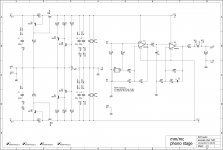
The S-Reg originally had capacitors C3,C4 which essentially lowered the output impedance (and the output ripple) by increasing the feedback.
These capacitors are removed in all the currently shipping boards. The original S-Reg board had them though, as did the CrystalFET.
The output impedance with the caps connected is about 1-2 ohms. Without, it's about 20-25 ohms.
If anyone is interested in the experiment, it is a simple matter to connect a 10-100 uF capacitor across the 10 k resistors (R9,10 in the schematic below, shown as 11.5k) and see if you hear any improvement or loss.
Btw the capacitors were removed for the following reasons,
1. Additional ripple rejection was not needed.
2. Additional feedback did not sit well with me as something you want to connect to an opamp which is already loaded up to the gills with negative feedback.
3. The capacitance could stress the transistors Q7,8 on start up by putting a large voltage across the base-emitter terminals.
4. It seemed to make no difference either way and I needed the board real estate.
I have a couple of Rev. 1.0f boards. So you are advocating omitting C3, C4 on these right?
Are there also any cap. changes to the 400 and Emerald boards that I might have missed?
I'm saying they were there on the S-Reg boards, they improve the regulator output impedance, but I'm not bothering with them on S-Reg built into the Phonoclone 4 and Emerald boards. Consider them optional.
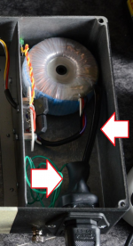
Re the whole class II thing, I notice (see attached) that the internal power wire to the transformer is made up of regular extension cord, so that's ok, and the IEC socket is all covered in heatshrink. Those are the only parts anyone making low voltage diy audio have to be really concerned about, as the transformer itself is certified by the manufacturer. If your build isn't formally "double insulated" it's close enough from an informal safety point of view. Officials may have a different opinion should you ever seek UL certification however.
Re the whole class II thing, I notice (see attached) that the internal power wire to the transformer is made up of regular extension cord, so that's ok, and the IEC socket is all covered in heatshrink. Those are the only parts anyone making low voltage diy audio have to be really concerned about, as the transformer itself is certified by the manufacturer. If your build isn't formally "double insulated" it's close enough from an informal safety point of view. Officials may have a different opinion should you ever seek UL certification however.
Attachments
FYI Air can also be one of the insulators.
Classes and types of medical electrical equipment
In practice, the basic insulation may be afforded by physical separation of live conductors from the equipment enclosure, so that the basic insulation material is air. The enclosure material then forms the supplementary insulation.
Classes and types of medical electrical equipment
error in Emerald BOM
R8 and R9 were mislabeled in the BOM list on both the 10c and 10s worksheets. The schematics were always correct.
R8 = 2.49k
R9 = 93.1k
Revised files have been uploaded to the website. 10c6 and 10s9 or later BOMs are correct.
Sorry about that. I didn't follow my own numbering protocol on the Emerald schematic, but assumed I had when I copied the base BOM over from the Phonoclone originally. I'll try to send out the new BOM to everyone who I sold boards to.
Attachments
- Home
- Source & Line
- Analogue Source
- The Phonoclone and VSPS PCB Help Desk