You don't the caps in the power supply, and it may sound better without them.
Do you mean you don't WANT the caps in the power supply box or don't NEED the caps there? In other words, is it somehow bad to do that? I haven't used my VSPS300 in a little (it's in the barn where I'm building a listening room) but I think I added caps in the PS thinking to keep as much AC out of the signal circuit box as possible. I wasn't looking for smoothing or regulation, of course, just to send a somewhat flattened supply.
You must send good quality DC current down the umbilical to the receiving enclosure.
That requires at least the first stage smoothing capacitance in the transformer plus PSU enclosure.
Having supplied good DC, to the second enclosure, the local supply rail decoupling will have to meet the demands for Mid Frequency and High Frequency current.
The DC then has the job to recharge that decoupling, preferably before the next transient demand comes along.
Andrew, this is going to be one of those rare case where I'm going to have to disagree with you.
Sorry about leaving out the word "need" in "You don't need the caps in the power supply, and it may sound better without them." Nothing breaks if you add them, but there little reason to have them either.
My phono stages have 1000uF per rail per board, so the diodes see 2000 uF per rail typically, and peak charging currents of say 200 mA will run from the diodes to the caps and back again though the power umbilical.
If you add an additional 1000x4 uF in the supply the AC currents flowing through the umbilical are halved, but at the same time you are loading the diodes and transformer with double the capacitance.
I don't think any of that matters either way. I do think it consistently sounds better with no capacitance in the power supply though, and as little primary filter capacitance as needed all placed as close to the amplifier circuit as possible.
It's simple enough experiment to try and see which you like better.
My Emerald build
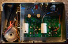
I have completed an Emerald build using evaluation boards.
As can be seen from the photo the boards and complete power supply are housed in a single enclosure. The RJM rectifier board has been used and a coated lead sheet shields the amplifier from possible stray mains radiation.
I have used just one S-Reg supply to feed both boards - making it possible to easily adust the 2 V+ and 2 V- rails to within 0.1V of each other.
Nichicon FG bipolars are used throughout and the 4 opamps are all OPA27's
Switches for mm/mc and load R are located on the rear panel for convenience.
I have built several examples of all RJM phono amps with the exception of the mc only phonoclones and have to say, in my opinion, that the Emerald is easily the best sounding of the bunch!
Thanks and congratulations Richard!
Dutch Keith
Attachments
Very good work. I'm glad you're happy with the sound. It makes me regret having bought the VSPS 400 boards (I have the VSPS 300 running). I would have bought these, but they came to light after the VSPS 400.
That configuration of separating the passive RIAA HF and active LF convinces me more.
But it's done.
What I find strange is that you have fed the two plates with the same source.
This does not influence the performance ?.
The other thing is that I do not see the screw of the turntable mass cable.
Regards and enjoy
I don't think any of that matters either way. I do think it consistently sounds better with no capacitance in the power supply though, and as little primary filter capacitance as needed all placed as close to the amplifier circuit as possible.
It's simple enough experiment to try and see which you like better.
OK, but it does seem counter-intuitive to me. Do you have any theories why that would be? As a mostly tube-builder, I generally aim for low impedance power supplies and as much capacitance as I can use while meeting that goal. I admit I don't know much about, or understand, those little silicone versions of tubes much less op-amps.
............That configuration of separating the passive RIAA HF and active LF convinces me more.
But it's done.
What I find strange is that you have fed the two plates with the same source.
This does not influence the performance ?.
The other thing is that I do not see the screw of the turntable mass cable.
Regards and enjoy
Very good work. I'm glad you're happy with the sound. It makes me regret having bought the VSPS 400 boards (I have the VSPS 300 running). I would have bought these, but they came to light after the VSPS 400.
That configuration of separating the passive RIAA HF and active LF convinces me more.
But it's done.
What I find strange is that you have fed the two plates with the same source.
This does not influence the performance ?.
The other thing is that I do not see the screw of the turntable mass cable.
Regards and enjoy
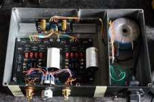
As I said with one S-Reg feeding two boards you can perfectly match all the rails. Maybe there is a theoretical reason (which I can't think of) for using two regulators but my configuration sounds just great to my ears.
On the photo you can see an experimental build using VSPS 200 boards fed by a single S-Reg. You can also see that I do use a ground lug. This is a simulation of the 400, if you like, and it sounds brilliant!
Attachments
Pokerback47, it had not occurred to me to do this. I'm going to try to do it, but by sharing the s-reg, each plate has half the capacitance.
Anyway, if you say it sounds good, I'll do it.
If you compare the VSPS with Esmerald, what difference do you find?
I see strange the way you connect the GND. It is in the power input and in the audio input-output. On both sides you connect to the chassis.
But if there's no earth loop, it's fine.
Anyway, if you say it sounds good, I'll do it.
If you compare the VSPS with Esmerald, what difference do you find?
I see strange the way you connect the GND. It is in the power input and in the audio input-output. On both sides you connect to the chassis.
But if there's no earth loop, it's fine.
Last edited:
What I am saying is based on my personal experiences. It's worth a try definately and would like to hear if it works for you. One S-Reg configured for a maximum load current of 25 mA, by the way, has more than enough capacity for two mono boards, drawing about 8 mA each.Pokerback47, it had not occurred to me to do this. I'm going to try to do it, but by sharing the s-reg, each plate has half the capacitance.
Anyway, if you say it sounds good, I'll do it.
If you compare the VSPS with Esmerald, what difference do you find?
I see strange the way you connect the GND. It is in the power input and in the audio input-output. On both sides you connect to the chassis.
But if there's no earth loop, it's fine.
The major advantage of the Emerald is obviously its mc functionality. The VSPS 400 comes very close to the Emerald with mm carts. Maybe the Emerald just about shades it but I don't really know because I haven't compared them with identical OpAmps.
Yes you spotted the green wire from the mains earth connector. Its not shown but the connection to the chassis ground lug was later made defeatable with a toggle switch. My reason for doing this was to provide a safety earth path when using vintage non-earthed turntables. No problems with an earth loop in my system either way. Good luck and have fun!
Take another look at my emerald photo. The red toggle switch at the back makes or defeats the connection mains earth to ground.....I see strange the way you connect the GND. It is in the power input and in the audio input-output. On both sides you connect to the chassis.
But if there's no earth loop, it's fine.
An externally hosted image should be here but it was not working when we last tested it.
I was referring to what is marked with red. RJM recommends connecting the GND of the plates to the GND screw where the mass cable of the turntable arrives, but I see that you have connected in 5 places.
Jose is right: you've actually connected the chassis to the circuit common multiple times on each board, once through the GND pad and once through the COM pad. These are already connected internally so only one of these needs to connect to the chassis. Normally that's the GND of each board, but it doesn't matter you could use COM if you want. I don't recommend both but I doubt it makes much difference.
It also doesn't matter if the connection to the chassis is made locally at the standoff or pulled together at the TT earth stud. By habit I've always use the earth stud.
With these builds with built in power supply the chassis is normally also connected to earth. This can cause problems since the audio returns (IN-, OUT-) are now connected to earth in the phono stage, and they are also going to be likely connected to earth in the preamp and amp as well. Potential for ground loops. A switch to defeat the earth is a solution, but probably puts you into conflict with safety codes. The real fix is to use a separate power supply so the phono stage chassis doesn't have to have a dedicated connection to earth, or, alternatively, lift the GND from the chassis/earth using a humbuster. (the latter I haven't tried by the way)
OK, but it does seem counter-intuitive to me. Do you have any theories why that would be? As a mostly tube-builder, I generally aim for low impedance power supplies and as much capacitance as I can use while meeting that goal. I admit I don't know much about, or understand, those little silicone versions of tubes much less op-amps.
I don't really understand why, no. It seems to be the case that everything (regulator, capacitors) need to up as close to the amplifier as possible. Why adding additional capacitance 1-2m away should make things actively worse I honestly have no idea.
Still, my experiences have been quite consistent going way back. Moving the regulation out to an external supply, or adding a second regulator to an external supply, or adding filter capacitance anywhere off the main boards, are all net negatives.
Maybe there is a theoretical reason (which I can't think of) for using two regulators but my configuration sounds just great to my ears.
That one at least is easy to answer: crosstalk.
The regulators have finite output impedance, somewhat deliberately the S-Reg's is fairly high, about 20 ohms ... at least at low frequencies where the bypass caps haven't kicked in this is seen directly by the op amp.
So signal currents drawn by one channel will generate a voltage as I*(20 ohms) on the power pins of the other channel, which is copied onto the output attenuated by the PSRR but amplified by the gain.
So worst case you lose a bit of stereo definition in the bass, but chances are it's not noticeable.
If the channels were isolated behind separate regulators, even if they shared a power supply the crosstalk would be an order of magnitude at least lower.
Last edited:
- Home
- Source & Line
- Analogue Source
- The Phonoclone and VSPS PCB Help Desk