laplace((75µ*s+1)*(3183µ*s+1))/((318µ*s+1)*(3.18µ*s+1))/{10}
Richarg. I just play with LTSpice. What I thought was to base myself on the RIAA generator that Calvin gave me and modify in reverse. What multiplied it made it divide.
Therefore, the .asc file can not be found.
I show you the formula that emerged after the modifications.
Richarg. I just play with LTSpice. What I thought was to base myself on the RIAA generator that Calvin gave me and modify in reverse. What multiplied it made it divide.
Therefore, the .asc file can not be found.
I show you the formula that emerged after the modifications.
Here's a simplified version.
Removing the Allen Wright 4th time constant, the laplace transform becomes,
laplace((75µ*s+1)*(3183µ*s+1))/((318µ*s+1))/{10}
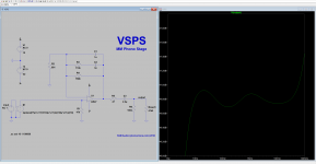
Insert the transform between the voltage generator and the VSPS input and the circuit output is the gain multiplied by inverse RIAA response.
It's convenient for working out which circuit values give the most linear response. Note that is it not a simulation of the actual cartridge, as the output impedance of the coils is not modeled.
Removing the Allen Wright 4th time constant, the laplace transform becomes,
laplace((75µ*s+1)*(3183µ*s+1))/((318µ*s+1))/{10}
Insert the transform between the voltage generator and the VSPS input and the circuit output is the gain multiplied by inverse RIAA response.
It's convenient for working out which circuit values give the most linear response. Note that is it not a simulation of the actual cartridge, as the output impedance of the coils is not modeled.
Attachments
Dead Op amps?
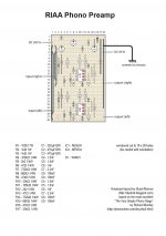
Hi. About two years ago I had built the vsps on veroboard. Not my design, all I did was just copying the following project:
Making an RIAA/phono preamp | DIY Strat (and other guitar & audio projects)
My plan was to revive my old cheap turntable, but to my dissapointment, I found out that my cartridge was broken, so I could not test if my build was working. I did not replace it and I gave up my vinyl ambitions.
Now I am planning on buying a used turntable, but that would require a working phono preamp.
So, in order to find out if my vsps was working, I used 2 9volt batteries (the initial transformer is not available) and since I had no phono, I connected my smartphone, instead of a phono in line in, and my amp to the line out. If I had an amplified sound (well, not the right kind of sound) I would guess that my vsps was working. But that's not the case.
That is what happens:
Sound is coming out just as it should, I mean like no circuit is attached in the line in and out of the preamp. It is like my phone is connected directly to the amplifier.
The preamp seems to have no affect on sound. Either powered on, either powerd of, I am still getting the same sound.
Resistor values, capacitors are double checked, so is the layout. All joints are OK and my veroboard layout seems ok.
Could it be that opamps are "dead"?
Maybe dual 9 volt is not enough?
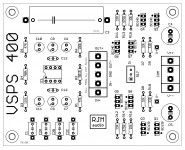
Below is the layout I used (without the psu part):
Hi. About two years ago I had built the vsps on veroboard. Not my design, all I did was just copying the following project:
Making an RIAA/phono preamp | DIY Strat (and other guitar & audio projects)
My plan was to revive my old cheap turntable, but to my dissapointment, I found out that my cartridge was broken, so I could not test if my build was working. I did not replace it and I gave up my vinyl ambitions.
Now I am planning on buying a used turntable, but that would require a working phono preamp.
So, in order to find out if my vsps was working, I used 2 9volt batteries (the initial transformer is not available) and since I had no phono, I connected my smartphone, instead of a phono in line in, and my amp to the line out. If I had an amplified sound (well, not the right kind of sound) I would guess that my vsps was working. But that's not the case.
That is what happens:
Sound is coming out just as it should, I mean like no circuit is attached in the line in and out of the preamp. It is like my phone is connected directly to the amplifier.
The preamp seems to have no affect on sound. Either powered on, either powerd of, I am still getting the same sound.
Resistor values, capacitors are double checked, so is the layout. All joints are OK and my veroboard layout seems ok.
Could it be that opamps are "dead"?
Maybe dual 9 volt is not enough?
Below is the layout I used (without the psu part):
Attachments
Hi. I've been reading about the advantages of preamps with split RIAA. First stage low gain (I think this gives better headroom) with acute passive cut and active second stage for low frequency accentuation.
I am acquiring parts to assemble VSPS400, since I have purchased the PCBs.
But before assembling it I have repented and I have convinced myself to assemble Esmerald MM MC.
Therefore, I am going to order the Esmerald PCBs.
I am confident that I will win in a better sound.
I am acquiring parts to assemble VSPS400, since I have purchased the PCBs.
But before assembling it I have repented and I have convinced myself to assemble Esmerald MM MC.
Therefore, I am going to order the Esmerald PCBs.
I am confident that I will win in a better sound.
@yianemma Yeah, with the correct layout that is quite literally impossible. There is a 5 mm air gap between input and output signal when the op amp is removed.
(thought: do you have the + and - of the inputs and outputs mixed up?)
@alpuy From a technical perspective the all-active single gain stage design would be superior if the amplifier block could handle it and there were no egregious layout issues with noise coupling &c. Once you decide to move to a two stage design, with a view to lowering distortion and improving layout safety margins, then you have to choose where to distribute the RIAA eq. elements: 1st stage, 2nd stage, or middle usually. That's where opinions diverge since which is best depends on what - and at what frequencies - you are most concerned with optimizing.
Emerald runs (1st stage flat, low gain) (passive LP filter) (2nd stage active, bass boost). Essentially it splits the two-stage dividend between noise and headroom.
But it is what I have concluded. Better headroom, less possibilities of saturation, better handling in high frequencies.
That's why I'm leaning for Esmerald.
Or you say that having the VSPS400 PCBs is better assembled instead of Esmerald ?.
It happens that I have become a fan of the DIY of phono pre.
That's why I'm leaning for Esmerald.
Or you say that having the VSPS400 PCBs is better assembled instead of Esmerald ?.
It happens that I have become a fan of the DIY of phono pre.
I meant that strictly from a headroom/noise aspect there is nothing inherently bad about a single-stage active RIAA design.
The Emerald should be superior from a distortion aspect, since it is using two op amps to amplify the signal rather than one - there is greater open loop gain available to apply to the feedback. Configured for 36 dB or so overall gain however there probably isn't much advantage over a regular VSPS - the difference is felt more dramatically once a midband gain above 40 dB is called for.
The take home is the Emerald is not going to be any worse than a VSPS as an MM phono pre, while for minimal extra BOM it nets you a far more flexible phono stage - aka it is also is as good as a phonoclone MC phono pre.
Ok, Richard, I understood.
When I buy a MC magnetic capsule (and a better turntable), it will be worth it to make Esmerald or Phono clone.
Meanwhile I would not notice an advantage over the VSPS400. Until I assemble it I continue with VSPS300 (which I am very happy with).
Thanks and I will continue the subject as I have done so far.
@yianemma Yeah, with the correct layout that is quite literally impossible. There is a 5 mm air gap between input and output signal when the op amp is removed.
(thought: do you have the + and - of the inputs and outputs mixed up?)
No offense yianemma, but I had to laugh my a** off when reading rjm's comment...
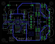
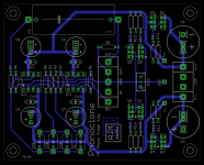
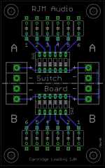
Preview (tentative) of the next board revisions. I'll be ordering new Switchboards soon, the others probably in 3-6 months time.
Apart from very minor and cosmetic changes to the traces, the main changes are to the silkscreen, mostly the electrolytic capacitors and I/O - the SwitchBoard silkscreen has been edited to make it clearer that the channel I/O is split down the middle of the board. The Sapphire is unchanged.
Apart from very minor and cosmetic changes to the traces, the main changes are to the silkscreen, mostly the electrolytic capacitors and I/O - the SwitchBoard silkscreen has been edited to make it clearer that the channel I/O is split down the middle of the board. The Sapphire is unchanged.
Attachments
- Home
- Source & Line
- Analogue Source
- The Phonoclone and VSPS PCB Help Desk