Yes, quite a lot of really odd stuff in that image, IMO.I still don't understand that gouge. It looks like it was made with a sharp tip, a tip much sharper than a stylus would be. Normally the stylus is too large to get to the bottom of the groove.
The way the image flattens the groove, it's a little difficult to tell what the gouge is like. Is it up the wall a few microns from the bottom of the groove? Would something sharp be needed to plow a row like that, or is it not as it appears?
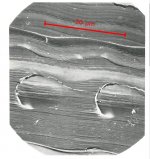
Strangely, there's no scale on the image. But we can deduce a scale, because we're told it is for the 10kHz test band of Decca SXL2057, from which we can identify the 50 µm modulation wavelength - as marked up in the attached image.
And that's where the fun starts.................
We're told the SEM image is a view of the groove from above, which seems correct to me. So we can measure dimensions, knowing the groove is a 45 degree V viewed from above.
First thing that strikes as odd is groove width at the top of the record, nearly 100um, about twice the normal stereo groove width. OK, it's a test record so maybe that's plausible, but possibly not............
Secondly, amplitude of groove modulation is far too big to be Decca SXL 2057 10kHz track..........it should only be about +/- 1µm, but is about +/- 3 times that......... so it doesn't look like Decca SXL 2057 should, IMO, and therefore probably isn't........?!?
Spacing between contact centres on respective walls works out at about 28 µm, that is consistent with about 20um (0.0008 inch) radius spherical which seems plausible.
The gouge feature, and the depression features, measure about 14µm and 28µm in height respectively, and IMO that's not plausible as the contact marks of a 20um radius sphere, unless impressed at very high force to the point of effectively inscribing.
So there's a forensic challenge: make the factual features of the image fit the description as we are told it. IMO, quite a few things we've assumed or been told need to be corrected......... an award for any self-consistent answer !
LD
Attachments
OK, here's my 2p worth of speculation:
Test record isn't Decca SXL2057 10kHz band. The scale, deduced by top groove width, is about twice as big as that shown in the markup. The stylus is a fine radius, about 0.0005 inch or smaller spherical, VTF is very high, and cartridge suspension very stiff. Or a steel needle 78rpm point type with 78rpm type suspension might do it........
LD
You are not suggesting (shock) that Decca set up this test to show their Deram in a good light?
") It's hard to know what was going on, but I doubt duplicity - genuine 1st class muck up, perhaps.....
It's hard to know what was going on, but I doubt duplicity - genuine 1st class muck up, perhaps.....The page you linked in #1366 definitely states Decca SXL2057 10khz band 5cm/s one channel at 11" (14cm diameter).
Then wavelength of that recording is certainly 48.9 µm (please re-double check?) so we can safely draw a scale bar on that SEM, as I posted.
Trouble is we can then measure amplitude of groove modulation, and show it is much too big to be Decca SXL2057. 5cm/s@10kHz should be an amplitude of (velocity/ω)/sqrt(2) ie about 0.56µm rms laterally and vertically - but one can see from the SEM and the scale bar derived from wavelength the modulation amplitude is much bigger than it should be............
.......what else is there to conclude than the SEM doesn't match the test record description ?
Also, the overall groove width at the top of the record is unusually big, nearly 100µm, about twice or more normal.......... based on deriving scale from wavelength.
I doubt that record can be as described.
It clearly is a single channel modulation, but other than that without knowing where it is on the record, it's impossible to say much more, other than wavelength is probably really about 25 µm, which would be really tight........ and the contact points inc gouge are very low - based on normalising to groove top width.
And upon such things apparently rests the basis of decades of opinion......
LD
Last edited:
I mean 14cm radius, of course, and that is what I used in calcs !:........linked in #1366 definitely states Decca SXL2057 10khz band 5cm/s one channel at 11" (14cm diameter).
LD
OK, here is my take on it.
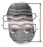
Since there is no scale, we have to assume the width of the groove. RIAA specs say 0.0022-0.0033 inches wide. Let's go half way, 0.0027" or about 68 microns across.
From there we can measure the artifacts seen in the SEM. See image below.
The gouge is about 9µ away from the bottom (center )of the groove, and roughly 8µ wide. That seems about right for the contact spot made by a conical stylus of an 18µ radius.
The damage bumps on the other side are 13µ from the bottom of the groove, and 13-15µ wide. They are placed where to grove gets narrow, so may be from the stylus riding up the wall a little at those narrow points.
Why the difference on the two sides, I don't know. Modulated vs Not?
Attachments
That is also what I found, based on the above. 25-26µmwavelength is probably really about 25 µm,
Then the test record wasn't Decca SXL 2057...........That is also what I found, based on the above. 25-26µm
So what was it ? And what confidence in other conditions?
This is not unusual, IME, that such things appear not to stand scrutiny, even when they are pivotal. One only has to scratch the surface ('scuse the pun)...............
LD
Last edited:
No comment on which test LP it is, I don't know them personally.
But I do think that the damage artifact fall where they should, given a standard conical stylus. It took some looking and head scratching to understand what is shown, but I get it now. Don't know why the damage occurred, but it does look properly placed.
If the track is at about 10" in diameter, what frequency would result in a 25µm wave length?
If the 'contact regions' are corrected separated, then the groove top width is abnormal, and even then modulation amplitude is too big for the record to be SXL 2057................But I do think that the damage artifact fall where they should, given a standard conical stylus.
About 50 µm is normal for a stereo groove top width..........I reckon if one normalises to that, the contact points are also low?
It's an enigma.
I really think one has to surrender the ideas that the test track was SXL2057, that a standard stylus was used, and that the VTF described was used.
Yes, as you say about 17kHz. But if the record's not SXL2057 we can't know what radius the sample was taken from. All we might say is that 25 µm wavelength and about 3µm amplitude would be very tight and at an extreme limit of trackability no matter where it is on the record, IMO.If the track is at about 10" in diameter, what frequency would result in a 25µm wave length?
LD
Last edited:
That's what we need to know for sure. The only info I could find was an old RIAA standard for 7". 10" and 12" discs which gives monophonic groove width as 0.0022"-0.0033". Stereo minimum 0.001"About 50 µm is normal for a stereo groove top width..........
Where did you find the 50µm width? That would be about 0.002", which I could adjust to.
Thank you Firesign Theatre!
I've had a browse around of SEM images of grooves. Many with scales seem to indicate a groove width of 75-80 microns. Here are some good ones:
High Mag Vinyl Pics | Steve Hoffman Music Forums
If the scan from the book is 80µm wide, that would change the wavelength seen.
I've had a browse around of SEM images of grooves. Many with scales seem to indicate a groove width of 75-80 microns. Here are some good ones:
High Mag Vinyl Pics | Steve Hoffman Music Forums
If the scan from the book is 80µm wide, that would change the wavelength seen.
Here is Decca SXL2057 cover.
Back cover
It says Level at 1 kc/s=1cm/sec RMS. Is that in any way helpful to measure amplitude ?
Regards.
Back cover
It says Level at 1 kc/s=1cm/sec RMS. Is that in any way helpful to measure amplitude ?
Regards.
Thanks, Hiten. Yes, one can deduce modulation amplitude from that information, as follows.Here is Decca SXL2057 cover.
Back cover
It says Level at 1 kc/s=1cm/sec RMS. Is that in any way helpful to measure amplitude ?
Regards.
1cm/s@1kHz rms implies 4.81cm/s@10kHz rms physical (RIAA curve)
Modulation amplitude = ( peak modulation velocity / ω ) [m]
At 10kHz ω = 2*pi*f = 62832 [s-1]
Peak modulation velocity = 4.81cm/s * sqrt(2)= 0.0681 [m/s]
Modulation amplitude = 0.0681/62832 = 0.0000011 [m] rms
Modulation amplitude = 1.1 µm rms
-----------------------------------
Direction of modulation of Decca SXL2057 is normal to one groove wall
Therefore lateral modulation of Decca SXL2057 10kHz band = 1.1/sqrt(2) = 0.77 µm peak
And vertical modulation of Decca SXL2057 10kHz band = 1.1/sqrt(2) = 0.77 µm peak
-------------------------------------
Either way of looking at calibration/scale, the SEM appears to show modulation far greater than this..............
I've re-doubled checked, but please do so too.
LD
Last edited:
Thanks, Pano.Thank you Firesign Theatre!
I've had a browse around of SEM images of grooves. Many with scales seem to indicate a groove width of 75-80 microns. Here are some good ones:
High Mag Vinyl Pics | Steve Hoffman Music Forums
If the scan from the book is 80µm wide, that would change the wavelength seen.
I think one has to be careful to only look at grooves that are definitely stereo, because a few of those show are mono which are wider. There is no average or target stereo top width spec, AFAIK. Here's some more, and I think if one looks at stereo only, for those SEMs which have scales, it seems to work out about 50-60um or so, IMO.
https://thevinylfactory.com/news/incredible-photos-of-record-grooves-under-an-electron-microscope/
For the SEM image at issue, if one uses the 50 um modulation wavelength as a scale indicator (as if it were SXL2057), then top width would work out about 90 um or so........it's not impossible, esp since it was a test record, but along with other pointers it seems to suggest something's wrong, IMO.
LD
- Home
- Source & Line
- Analogue Source
- mechanical resonance in MMs