Pass DIY Addict
Joined 2000
Paid Member
Pass DIY Addict
Joined 2000
Paid Member
I am not sure if I'll do PtP or build on a small perfboard. I want to lay everything out and see how compact I can make it. I was thinking of building 4 separate regs and mounting them to a copper bar and then fixing the bar(s) to the chassis. There isnt a whole lot of room under there, but it should all fit.
Since you asked, what are your thoughts?
If only I had made all of my purchases in units of 50 pieces what I started down this DIY path 15 years ago")
Since you asked, what are your thoughts?
If only I had made all of my purchases in units of 50 pieces what I started down this DIY path 15 years ago
Don't bother with separate regs... with the transformer removed, DC on the umbilical, and a super precise reg (the TPR) in the table, it will be better than 99.99% of all the SL-1200 PSU out there.
Dimkasta -- It that purple PCB set the external PSU and TPR? Will the small PCB mount inside the turntable and be able to heatsink? If yes, can you share the gerbers or have a group buy? I'm in for at least 2.
Dimkasta -- It that purple PCB set the external PSU and TPR? Will the small PCB mount inside the turntable and be able to heatsink? If yes, can you share the gerbers or have a group buy? I'm in for at least 2.
Pass DIY Addict
Joined 2000
Paid Member
I'm working on a small perf board prototype for the regulator, part of the challenge is figuring out what dimensions will fit inside the transformer hole. When it's finished, it should be more smooth and quiet than the power supply for my current phonograph.
Attachments
Pass DIY Addict
Joined 2000
Paid Member
I'm working on building my tracking preregulator and am using some green 3.0v LEDs: C4SMC-GGF-CX14Q8S2 Cree, Inc. | Mouser
I am using 7 of them to create a 21v reference, which actually measures 21.3v on the output of the regulator. But, when I measure the forward voltage drop of this same set of LEDs, it totals only 18.9v (they average about 2.72v each).
What is going on here? I'm sure this is something rather basic, but I can't seem to find anything about this in what I have read.
The output voltage will be the value of the diode string +1.25V (the voltage that the regulator tries to keep between the ADJ and OUT pins)
Also, diodes usually measure low on the meter, as the current is really low.
The other question is do you have the LEDs in the proper direction? Zeners are reversed-biased, LED are forward biased...
But all of that is irrelevant, you have the desired output voltage. Carry on.
Also, diodes usually measure low on the meter, as the current is really low.
The other question is do you have the LEDs in the proper direction? Zeners are reversed-biased, LED are forward biased...
But all of that is irrelevant, you have the desired output voltage.
Carry on.Pass DIY Addict
Joined 2000
Paid Member
Thanks for the details, Jim. I'll double check the LED orientation tonight and see what I find.
I also played around with some zeners and found some strange things which makes me think I overlooked that they are reverse-biased. With a 19.2v power supply into my regulator and a 5.6v zener voltage reference, my regulator provided 15.3v on the output and a 3.3v zener provided 18.5v out.
How critical is the 21.0v reference for the SL-1200? Should I just keep it at the 21.3v or should I mix in other LEDs to bring this down to 21.0v?
I have just finished building filtered PSU and regulated unit as described in this thread. I use string of zener diodes 11V and 8.2V, I got about 20.3V from the regulation. A little bit lower than spec. However before I connect to the deck, I would like to clarify something first.
1. According to the schematic, the on-board regulator consist of Q1 Q2 Q3 and some resistances, I just take Q1 out and replace it with regulator unit and leave everything else in place. Is that correct?
2. If I don't want to take the on-board bridge diode out, can I just solder the +V from filtered PSU to input pin (J1) of the regulator? I suppose that would by-pass the diode bridge without taking them off the board.
Thank
Chatchai
Pass DIY Addict
Joined 2000
Paid Member
Are you going to point wire it or make a PCB?
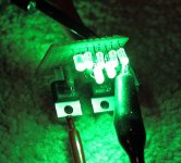
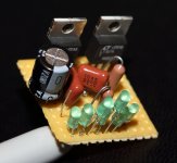
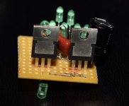
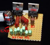
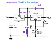
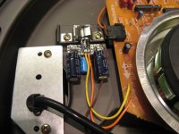
Here is my Tracking Pre-Regulator. It uses seven 3.0v 20mA LEDs as the voltage reference and the two LT317A military spec regulators measure about 21.0v on the output. I am making one for the motor and another for the motor control. They will sit side by side on a copper bar and live in the hole where the transformer came from. I didn't realize my LEDs would be as bright as they are - my platter might have an alien-green ring around it while it spins...
Attachments
Pass DIY Addict
Joined 2000
Paid Member
Will do, I'll post a few high-res images tonight. It was a bit of a trick to implement on perf board without needing to cross bare leads. I followed the diagram I posted, but it got complicated when I realized they had moved the pinouts in the diagram for the sake of neatness of presentation - you don't have that luxury with the devices in hand... The whole thing is just bigger the size of a quarter.
Pass DIY Addict
Joined 2000
Paid Member
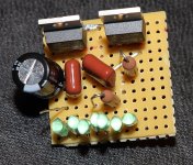
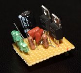
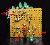
Here you go! Values are as follows:
R1 = 150R
R3 = 120R
R4 = seven 3.0v LEDs for 21v ref
Purple R = 10R
C1 = 0.1uF film
C2 = 0.1uF film
Input Cap = 100uF 63v (had on hand)
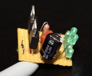
The wiring is a bit hard to see, so I attached lots of pictures. Too bad I don't have any equipment to measure how it actually performs relative to a "normal" regulator. The perf board measures 12x12 if you count holes. I put the regulators in row 3 to reduce the height of the board once I attach the regulators to the copper bar. Just ask if you have any questions!
R1 = 150R
R3 = 120R
R4 = seven 3.0v LEDs for 21v ref
Purple R = 10R
C1 = 0.1uF film
C2 = 0.1uF film
Input Cap = 100uF 63v (had on hand)
The wiring is a bit hard to see, so I attached lots of pictures. Too bad I don't have any equipment to measure how it actually performs relative to a "normal" regulator. The perf board measures 12x12 if you count holes. I put the regulators in row 3 to reduce the height of the board once I attach the regulators to the copper bar. Just ask if you have any questions!
Attachments
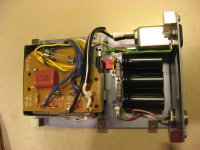
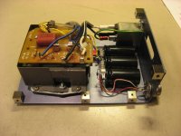
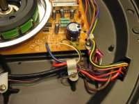
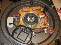
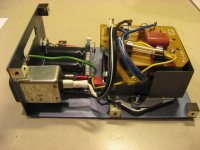
Hi. Just did the SL1200 external supply and internal reg mods on my son SL1200-MK2. Huge improvement Now with the table connected to a very low noise MC preamp, needle not on the vinyl, the table is as silent as a CD player, according to my son. Previously with the stock table we could here a AC hum at high volume. For the price and ease of modification, this is a must do mods for sure. See the included pictures. Internal regs is the simple LM317, external supply is re-using the table AC input PCB with the fuses, mounted over the stock transfo. Rest of the rectifier and CRC fileter is all point-to-point. I re-used the table On-Off switch to disconnect the supply dc once not used.
Now with the table connected to a very low noise MC preamp, needle not on the vinyl, the table is as silent as a CD player, according to my son. Previously with the stock table we could here a AC hum at high volume. For the price and ease of modification, this is a must do mods for sure. See the included pictures. Internal regs is the simple LM317, external supply is re-using the table AC input PCB with the fuses, mounted over the stock transfo. Rest of the rectifier and CRC fileter is all point-to-point. I re-used the table On-Off switch to disconnect the supply dc once not used.Attachments
Pass DIY Addict
Joined 2000
Paid Member
I am continuing to work on my Pearl and Sl-1200. Both will feature an outboard power supply. Sine the voltage requirements are about the same, is there any problem with using the same transformer (20vac), discrete rectifier, and filter caps (CRCRC) to feed both the SL-1200 and the Pearl? Both the pearl and the SL-1200 will have their own on-board power regulators.
- Home
- Source & Line
- Analogue Source
- Technics SL-1200 DC Power Supply