Pass DIY Addict
Joined 2000
Paid Member
Interesting idea with the Zen regulator, I hadn't considered that option. I was just looking for a way to burn a few volts, keep some of the heat out of the TT chassis, and/or be a little more kind to the newly installed regulator. It seems that the stock transformer is a little high at 40+V when only 20vDC is needed.
Hi,
instead of using a single 'overthetop' reg that still leaves the subassemblies able to interact with each other, why not use dedicated regs for at least the two most sensitive subassemblies (oscillator and speed regulator)?
What do You expext to achieve with a single overkill reg, that a typical linear reg can't?
I'd rather put effort into where there's a benefit and not for plain show-and-tell reasons.
I admit though that it requires to cut a few traces on the main PCB.
jauu
Calvin
It seems that the stock transformer is a little high at 40+V when only 20vDC is needed.
I don't disagree, and suspect it's so only one transformer part number could be used for 100V and 120V countries. But it works just fine and the transformer is shielded and (more importantly) soft-mounted, so might as well use it even if you put it in another box.
As for a 2nd reg, honestly I wouldn't bother. CRC (or better CRCRC) with large value R (5 - 10ohm) gets rid of so much noise and ripple on the line that you will be very surprised. The reg doesn't do much more for ripple, but does get rid of it's gnd point fluctuating as the AC varies.
If you haven't seen it before, here is the bible on using 317 in audio Using 3-pin regulators off-piste: part 1
If you are just dying to drop the extra volts look at part 4 and go for the 'tracking pre-regulator'. It needs about 5 volts of dropout to work, and easy use of the extra volts that we have in these decks.
Pass DIY Addict
Joined 2000
Paid Member
Calvin, I was re-reading your earlier post and the thread where Paul provides some instructions for his reg last night and came to this same conclusion. It makes sense to separate the motor drive from the timing circuits. I'll have to study Paul's diagram and directions a little more closely, but I'm not afraid of de-populating areas of the board and cutting some traces.
Jim, thanks for the link on regulators, I hadn't seen that before. I'm always on the lookout for useful details to tuck away so they don't get lost!
Jim, thanks for the link on regulators, I hadn't seen that before. I'm always on the lookout for useful details to tuck away so they don't get lost!
Pass DIY Addict
Joined 2000
Paid Member
Wow - continuing to dig, I am surprised at the volume of information and tweaks available for this TT! Calvin, I agree with your point about separating major components of the power supply. Good filtering and regulation seems especially important as my local power utility company has recently converted our neighborhood to using the TWACS system - it injects significant noise into the household AC supply every hour or so. This electrical noise creates audible noise in some of my audio equipment, my Class-D amp seems especially susceptible to this noise. 
So, here is the information that I have gathered about creating dual power supplies to separate motor drive from motor control.
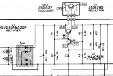
Remove original regulator components from the main board: R1, R2, R3, R4, R5, D1, D2, Q1, Q2, Q3, C1, C2, C5, and C6. Leave C3 in place. See attached PS schematic.
Separate motor drive from motor control by cutting the thick trace on the bottom of the PCB as indicated by Paul.
Create Outboard Power Supply: Jim's CRCRC or Zen v3 capacitance multiplier using the original transformer to provide ~26-27VDC (leaves a little more than 5V headroom for downstream regulators to work properly). This PSU will drive parallel regulators inside the TT:
Make one 21v tracking pre-regulator (thanks to Jim for the link!) for motor drive. Use stacked Zeners or LEDs for voltage reference.
Make second identical 21v tracking pre-regulator for motor control.
Maybe play with separate 5v and 9v4 supplies for IC302 and IC301 later on. DEXA regulators look interesting, though a bit more expensive than an LM317 with some support parts... The NewClassD web page provides directions for modifying output voltage for 9v4.
Have I missed anything?
So, here is the information that I have gathered about creating dual power supplies to separate motor drive from motor control.
Remove original regulator components from the main board: R1, R2, R3, R4, R5, D1, D2, Q1, Q2, Q3, C1, C2, C5, and C6. Leave C3 in place. See attached PS schematic.
Separate motor drive from motor control by cutting the thick trace on the bottom of the PCB as indicated by Paul.
Create Outboard Power Supply: Jim's CRCRC or Zen v3 capacitance multiplier using the original transformer to provide ~26-27VDC (leaves a little more than 5V headroom for downstream regulators to work properly). This PSU will drive parallel regulators inside the TT:
Make one 21v tracking pre-regulator (thanks to Jim for the link!) for motor drive. Use stacked Zeners or LEDs for voltage reference.
Make second identical 21v tracking pre-regulator for motor control.
Maybe play with separate 5v and 9v4 supplies for IC302 and IC301 later on. DEXA regulators look interesting, though a bit more expensive than an LM317 with some support parts... The NewClassD web page provides directions for modifying output voltage for 9v4.
Have I missed anything?
Attachments
Fantastic plan of attack!
I would suggest making a raw supply in the outboard box if you are going to use tracking per-regulators downstream. The argument against series series regs given in the 'off-piste' article, the same one talking about the benefits if the TPR, holds true here as well.
The CRC will get rid of the bulk (98%) of the noise, the first half of the TPR will deal with the line variances, leaving the second half of the TPR to live in it's own little perfect world and handle the load.
Beause that regulaotr will be so wonderfully isolated from the outside world, I imagine that a seperate motor control regulator would be quite superfluous. The total load is quite steady once the platter is up to speed. It's worth a try, but only after getting the TPS in the first, main position.
Pass DIY Addict
Joined 2000
Paid Member
40V ish under no load. A bit less once the platter is to speed. Never less than 30V.
And that's with (2) 10R resistors.
But honestly, just use up whatever parts and pieces you happen to have laying around that are in the general vicinity. There's nothing critical about this outboard supply. I used 6800uF and 10R purely as I had those values on hand.
And that's with (2) 10R resistors.
But honestly, just use up whatever parts and pieces you happen to have laying around that are in the general vicinity. There's nothing critical about this outboard supply. I used 6800uF and 10R purely as I had those values on hand.
One thing that I was thinking is that there might be some extra improvement in noise rejection if we keep the voltage drop across the regulators in more moderate levels. This will also help by allowing lower temperatures in the regulators, which in turn improves noise rejection.
My current CRCRC filter uses a reg instead of the second resistor, which effectively acts as a pre-regulator instead of just a filter.
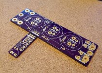
I will post a photo and some more info later today
My current CRCRC filter uses a reg instead of the second resistor, which effectively acts as a pre-regulator instead of just a filter.
I will post a photo and some more info later today
Hi,
I still don´t get it why you want to go such a complicated, costly way
You could still use the internal Regulator Q1-Q3 as it is a good regulator.
You could for example increase its output voltage to ~27V by increasing the value of R2 to 9k1.
You need to relace C3 by a cap with higher voltage rating.
But since the TT is probabely older than 10years it might be a good idea to change C3 anyway.
Then You can cut the traces to the motor supply, resp. the control circuitry and insert two LM317 regs. for the 21V supplies.
Much less effort, cost and hassle and it requires less PCB area.
jauu
Calvin
A few euros and minutes are not an issue for me. I spend much time and money on my diy anyway
10-15 euros for a few good-practice parts is not a bad deal...
Oh and careful increasing the voltage. I have already fried one chip... (accidentally at ~31V if I remember correclty but still....)
10-15 euros for a few good-practice parts is not a bad deal...
Oh and careful increasing the voltage. I have already fried one chip... (accidentally at ~31V if I remember correclty but still....)
Last edited:
Pass DIY Addict
Joined 2000
Paid Member
Does placing a larger cap (6800uF to 10,000uF) between regulators (if I were to replace the second R in a CRCRC) help prevent some of the trouble that results from series series regulators?
Looking closely at Paul's design seems to indicate that he did something similar to what Dimitri is suggesting. I see Paul's primary out-board regulator with the copper sink has a few large caps on it that I can only assume are used to feed downstream regulators that are mounted inside the turntable.
Looking closely at Paul's design seems to indicate that he did something similar to what Dimitri is suggesting. I see Paul's primary out-board regulator with the copper sink has a few large caps on it that I can only assume are used to feed downstream regulators that are mounted inside the turntable.
My first thoughts are that such a big cap after a regulator has two problems.
First, it shows a low ESR at the output of the reg which might create stability issues, and second, it virtually eliminates the load regulation functionality of the first regulator.
I would use a normal ESR 1000uF cap after the reg. What I use in my current design is a Nichicon KG
First, it shows a low ESR at the output of the reg which might create stability issues, and second, it virtually eliminates the load regulation functionality of the first regulator.
I would use a normal ESR 1000uF cap after the reg. What I use in my current design is a Nichicon KG
Pass DIY Addict
Joined 2000
Paid Member
Just a small divergence from the power supply topic: what should those dots around the perimeter look like while the platter is spinning? On my spinning platter, the dots as illuminated by the strobe look distinctly different than crisp, fixed dots. The edges of the dots look somewhat blurred and fuzzy as the platter spins. Almost like 'warbles' that vary from round to slighly ellipical, though they don't 'travel' at all. The overall pitch appears to be accurate, but the dots do wiggle around just a bit.
Is this fairly typical? Just asking because I don't know.
Is this fairly typical? Just asking because I don't know.
Hi,
increasing the output voltage does not fry the regulator but the opposite.
The reason is, that the voltage drop over Q3 becomes smaller and so does heat power loss. If you tried it and fried the Q, there must have been a different, like maybe a too large cap C3 drawing too much current at startup.
Its neither of benefit and more often than not a serious drawback to put large sized low-ESR lytics everywhere.
Let the Reg do what it is intended for. Its much better in smoothing out voltage ripple at low-to-medium frequencies than any cap could ever be. At elevated frequencies mostly ony other cap, be it film, tantal or ceramic are better suited than lytics. They are just good as energy storage.
As the current draw is quite constant here with a low dynamic range, there's no need for large capacitances at all. They'd be overkill, which is not only a waste of ressources but usually results in inferior outcome too.
jauu
Calvin
Is this fairly typical? Just asking because I don't know.
If the dots do not move left-right you are fine.
Calvin yes I was talking 31V after the reg
Pass DIY Addict
Joined 2000
Paid Member
If the dots do not move left-right you are fine.
Good to know, I won't give it another thought.
Next on the list are a cartridge and an order from Wayne. I want to listen to it stock before I really tear into it with mods...
Pass DIY Addict
Joined 2000
Paid Member
I am starting to plan/build my outboard power supply for the SL-1200. It will likely be a CRCRC for CLCRC in an outboard box with this tracking pre-regulator inside the turntable chassis:
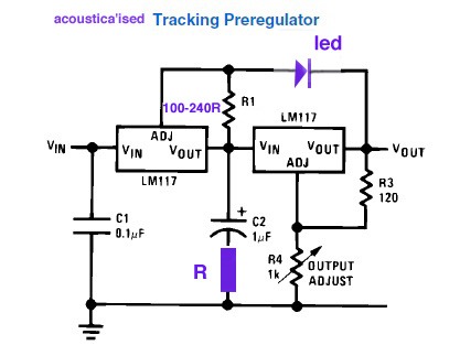
My question is, which size cap (if any) should come before and after this regulator?
Thanks!
My question is, which size cap (if any) should come before and after this regulator?
Thanks!
- Home
- Source & Line
- Analogue Source
- Technics SL-1200 DC Power Supply