I installed the reg using a 10v + 8.2v zeners + one 1n4007 (0,6v) for the reference
The difference was very big especially in the stereo image and the stage depth.
Caps are a 220uF panasonic FR in the reference and a 1000uF nichicon muse for the output. R1 is 100R
Next step is to add the pretracking reg and make it a bit better in layout because like this it is an accident waiting to happen
With max Vin at 27V, the LT10xx are a nonono with the stock transformer (~40V dc).
Vmax for the LT10xx is referring to the difference between input and output voltages. So 40V in to 20V out is still well within limits. I just put Pete Millett's low V regulator together using the LT1084 for my SL-1200 and it works great. I've started posting info here:
http://www.diyaudio.com/forums/anal...brackets-regulator-external-power-supply.html
You can also use the lower-voltage regulators at higher voltage with the adj pin standing off ground (via zener or something) by whatever voltage you desire - just be darn sure to use the protection diodes so the reg never sees the caps discharging across it on power-off.
Voltage regulators from EBAY
I have used this for the last year or so
High-Voltage Adjustable Regulator Module Based on TL783 | eBay
i took the transformer out and used it.Then the regulator module and some 4700uF caps i had after.New Van damme screened cord an desoldred the bridge and two caps,fitted it to the board,set the module for 30V and bingo!
Works like a clock.Measured 30,5 for about 10 hours ,steady as a rock.
You can also use this
Voltage Regulator Module, Output 5A / 1.5-32VDC, LM338 | eBay
with a toroid 2x9V connected to 18V to get 18-25V (Yes the technics can run from 18-25V as i have been told by Fidelity audio) and use it insted of the internal regulator.just remove the caps and resistors and the internal regulator as done in this thread.
PSU for Technics 1210
and solder the + - cords where the C3 used to be.
Set the module to about 21-22V and there you have it.
these modules comes free shipped and cost 13-26£.c
just add some transformer and caps and you are ready to go.
I doubt that they are any worse than the overpriced stuff you can buy from so called high end modification firms or persons.
It works perfectly belive me.
Good luck.
Hi,
the transformer voltage of the SL-1200mk2 and its heirs is vastly higher than needed.
Behind the regulator the supply rail measures 21V.
Adding 3V for the regulator itself any dc voltage from 24V on will suffice.
The 21V themselves would not be needed that high.
They only supply the motor driver IC, the AN6675.
This IC is also used -together with its partner control IC AN6680- in the SL-Q2, SL-Q3, SL-Q33 and some more.
In those players the supply rail is 12V.
What difference dose this make?
It only reduces the maximum motor coil current, which is used to correct for gross deviations from the set speed.
This happens at start up and maybe while scratching.
Under typical low- or undisturbed home hifi conditions the motor currents are very small and so are the regulating variances.
In other words is the higher possible torque of the motor only due to the higher supply rail and is to no advantage at all for home hifi useage.
The second IC of this Chipset, the control IC AN6680 is not supplied directly but over a resistor with different values for a 21V or 12V supply rail.
This only feeds an internal power circuitry that generates a fixed reference voltage for an external-to-the-IC voltage regulating transistor (Q201).
The output voltage of this regulator (9V) forms the real supply rail for the AN6680 and the FG-Generator circuitry.
In other words the control circuit generates its own dedicated supply rail.
With these infos in mind, where and how could modifications improve matters?
Taking the transformer out of the mechnical systems may put away with possible vibrations.
Replacing the tranny by a lowpower SMPS of 24-36V (or >=15V for the 12V models) may allow to keep the complete electronics inside the player's cabinet.
Other than that I could only think of artefacts of the control ICs supply current (maybe due to gnd-layout, where both ICs share traces) that influences on a very low level on the motor drivers supply rail.
Personally I don't see a requirement for oversizing supply capacitance, as there are only small current variations and it makes no difference at low frequencies down to dc to the supply rail impedance.
I'd rather opt for a low impedance regulator combined with a star-shaped system of supply rail traces (cutting rails and gnd traces and rerouting)
Pushing a bit further one may think about implementing dedicated regulators for the motor-IC and the control-IC and rerouting rails and gnd.
I think I'll do that on my actual project with SL-Q2 electronics even though I don't expect nearly as large improvements than some exaggerated(?) claims suggest.
The reason is imply the way the drive sytem works.
In contrast to some explanations there occur no large current pulses that somehow give the platter short and massive high-torque pushes, but only small and softly varying continuous currents and torque.
The currents and hence the torque are so low that they only make up for the tiny friction losses, added the drag of a cartridge needle and maybe a cleaning brush.
So, within a certain defined range of 'error' load, a weak-torque and a high-torque motor don't make any difference whatsoever!
It just increases the load range to within the PLL can hold the platter speed locked.
Which also implies that the stronger motor is not responsible for any sonic differences between the Technis models (actually the motor is identical, its just the possible higher currents that make it 'stronger').
Besides the mechanical time constants are always vastly larger than the electronic time constants, thereby effectively swapping/filtering out any ripple or wobble of the torque.
jauu
Calvin
Last edited:
Pass DIY Addict
Joined 2000
Paid Member
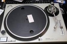
What a Great thread! Thanks so much for all of this awesome information. The FedEx guy just delivered my new toy and I see that I have a number of projects from which to choose to make some modifications! This deck was made in 1999 and has a few light scuff marks, but seems to be in overall nice shape.
Progress will be slow, but it looks like some upcoming projects include building a phono stage (I'm thinking of a Pearle 2), an outboard power supply, and replacing the tonearm and interconnect wiring. I also need a good entry- to mid-level cartridge. It will likely be the end of the year before I get time to do all of the things I'm interested in.
My ultimate goal is an all analog setup with a tube amp to drive a set of Tang Band full range driver speakers. So many fun ideas, so little time. Sigh...
Attachments
The Pearl 2 is fantastic, I can recommend it without hesitation. 
In my experience, the things you should do to the stock SL-1200 are,
Platter Mat - Not the stock rubber. Cork is very nice. As is the Acromat from Funk Firm. Most certainly no felt or slipmat.
Feet - even something as simple as placing vibrapods under the stock feet helps an awful lot. I am a huge fan of Isones. Expensive but not silly audiophile priced. Worth every penny.
Tonearm rewire - the stock tonearm wire in your arm is most likely corroded. Of course new wire is going to sound better.
PSU - It punches so far above it's weight that it's silly. A must do.
With PSU, a good mat and good feet you may, without hesitation, mount any cartridge on the table your heart desires. It can handle it, and with style, grace, and a rythm, timbre and tunefulness that you will never get on a belt-drive table.
Platter Mat - Not the stock rubber. Cork is very nice. As is the Acromat from Funk Firm. Most certainly no felt or slipmat.
Getting a decent mat is HUGE for the SL-1200. I've got a Herbies on my M3D.
jeff
Pass DIY Addict
Joined 2000
Paid Member
Thanks for the input, guys! I figure I have a few things to do and want to take some time to hear what the upgrades do for sound, so I want to plan things out in stages, such as:
1) Cartridge: I'd like to keep this in the $200-$400 range. I've been scouring the threads for which cartridges people have used with the Technics and it seems like there are a few popular choices: AT-150MLX, AT-440MLa, Stanton 681EEE, Denon DL103, Zu DL-103, and Ortofon 2M Blue/Bronze.
2) Build the Pearl - thanks for the photo guide, Jim! How much can the gain of the Pearl be controlled? Wayne's article indicates ~50dB of gain with the option for 60dB with a resistor mod, which seems to point at the low- to medium-output MC cartridges. If I go with a higher output MM (AT and Ortofon seem to have output that is 4-5mV), will I be able to adjust the gain of the Pearl down with a resistor change so as not to overwhelm downstream components?
These two items will get me to the point where I can listen. The TT/Pearl will input to a hot-rodded DCB1 as a front end to either a B3-F4 combo or an Aleph-J. An EL84 or 2A3tube amp project comes later... I have an in-progress set of TangBand 1772 speakers that I really like, may add a small sub, though.
Then I want to start working on upgrades with some time to listen in between:
1) KAB tone arm rewire, plus new RCA cables out
2) Outboard DC PSU & replacing the onboard 20v regulator
3) Platter Mat - currently have heavy stock rubber mat with a layer of cork. Have read lots of good feedback about Herbies and the Acromat.
4) Feet - currently have a DIY vibration table that provides three-axis damping, but the Isones look interesting. Got the wire feet from Shock-Tech at a military trade show a few years ago, but I'm thinking the TT may be too heavy for them.
Is it worth it to replace all of the electrolytics on the main PCB while I'm in there working on the PSU?
Attachments
1) Cartridge: AT-150MLX
Perfect.
2) Build the Pearl ... will I be able to adjust the gain of the Pearl down with a resistor change so as not to overwhelm downstream components?
Build it to the stock value. You won't need to turn it down, even with a strong cartridge.
The TT/Pearl will input to a hot-rodded DCB1
With a B1, you will never overwhelm anything past it.
1) KAB tone arm rewire, plus new RCA cables out
2) Outboard DC PSU & replacing the onboard 20v regulator
3) Platter Mat - currently have heavy stock rubber mat with a layer of cork. Have read lots of good feedback about Herbies and the Acromat.
4) Feet - currently have a DIY vibration table that provides three-axis damping, but the Isones look interesting. Got the wire feet from Shock-Tech at a military trade show a few years ago, but I'm thinking the TT may be too heavy for them.
1)Yes
2)Yes
3)Yes
4)Neat!
Is it worth it to replace all of the electrolytics on the main PCB while I'm in there working on the PSU?
Depends on it's age really, if it's mid-90's or newer there's really no reason to. If it's older but still working fine, don't bother.
Pass DIY Addict
Joined 2000
Paid Member
Pass DIY Addict
Joined 2000
Paid Member
Getting a bit off topic from power supplies, but I figured I would add this here rather than creating a new thread:
Last night I was playing around with the TT and noticed an intermittent and non-periodic grinding or scraping sound as the platter rotates. It lasts for less than one second and sounds a little "gravel-like" and then disappears. I am unable to cause it to happen by changing RPM speed with the power on, or by spinning the platter by hand with the power off. I presume this means I need to remove, disassemble, and clean (perhaps replace) the motor spindle. The ring magnet under the platter appears clean and does not have any debris stuck to it. Is there anything else I should look at? The platter itself appears to spin true, no vertical or horizontal deflection as it rotates and the visible part of the spindle appears steady (no wobble) as the platter rotates.
Thanks for any insights.
Eric
Pass DIY Addict
Joined 2000
Paid Member
Hmm... I'll have to dig more deeply into it shortly. Like with cars, diagnosing the intermittent problems is always most frustrating, but I'll find it.
My wife already makes fun of me by saying things like "The first thing most people do with products that have JUST arrived in the mail is DOESN'T usually involve disassembling them!"
My wife already makes fun of me by saying things like "The first thing most people do with products that have JUST arrived in the mail is DOESN'T usually involve disassembling them!"
Pass DIY Addict
Joined 2000
Paid Member
Ha - after 20 years, she just shakes her head and laughs at me while I'm holding my screwdriver...
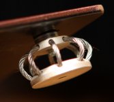
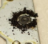
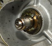
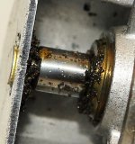
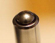
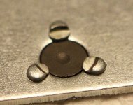
Taking things apart was definitely worthwhile. With a closer look, I found a small rounded blob of a metal fragment hiding on the magnet under the platter. I suspect this was the source of my intermittent noise. But I figured I would have a look more deeply into things and I'm glad I did. Here are some images of what the spindle mechanism before and after a good cleaning. I was surprised by the quantity of debris present and was pleased with how nicely everything cleaned up. With the exception of the shallow cup worn into the thrust pad, everything looks great now. A drop or two of oil makes everything spin noticeably easier than before.
Taking things apart was definitely worthwhile. With a closer look, I found a small rounded blob of a metal fragment hiding on the magnet under the platter. I suspect this was the source of my intermittent noise. But I figured I would have a look more deeply into things and I'm glad I did. Here are some images of what the spindle mechanism before and after a good cleaning. I was surprised by the quantity of debris present and was pleased with how nicely everything cleaned up. With the exception of the shallow cup worn into the thrust pad, everything looks great now. A drop or two of oil makes everything spin noticeably easier than before.
Attachments
Fantastic that you found the noise, and even better that you dug deeper and cleaned that gunk off the thrust pad!
I enthusiastically suggest getting the proper oil from KAB, it has a very high film strength so it stays on the bearing, but is light enough to be of genuine benefit.
(Might as well order an arm re-wire kit and the Technics overhang gauge while you're at it. )
I enthusiastically suggest getting the proper oil from KAB, it has a very high film strength so it stays on the bearing, but is light enough to be of genuine benefit.
(Might as well order an arm re-wire kit and the Technics overhang gauge while you're at it. )
Pass DIY Addict
Joined 2000
Paid Member
I'll be sure to get some proper oil from Kevin.
Back to the topic of DC power supplies, is it worthwhile to use an LC filter in the outboard supply to drop the power supply down a little, or to use a 25v regulator in the outboard supply and then take it down to 20v with another regulator inside the TT?
Back to the topic of DC power supplies, is it worthwhile to use an LC filter in the outboard supply to drop the power supply down a little, or to use a 25v regulator in the outboard supply and then take it down to 20v with another regulator inside the TT?
Series series regs don't really have any advantages except voltage reduction. The stock circuit had lots of volts thrown away in the regulator, so if you replace it with a 317 or something similar, it will work just fine.
I used CRCRC in mine for a reason, it's a really quiet filter. It's also quite lossy under load, but with as much overhead as the PSU has, it presents no issues at all.
But, if you are just dying to reduce the input voltage, just use a mosfet capacitance multiplier, with a Fet that has a large Vgs, say an IRF240 -- that will be an easy way to make 4.5V or thereabouts go away with little fuss. Look to Nelson's 'Zen Variations 3' for a schematic.
- Home
- Source & Line
- Analogue Source
- Technics SL-1200 DC Power Supply