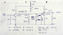
Schematic for my next version of simple Pacific
Sorry for my late reply, i had a lot of things going on. I cleaned up my whole circuit, fittet it in a metal cookie box, cleaned up the input and output cabling. I was thinking a lot about how to seperate signal grounds and "high current" grounds like from the cleanup capacitor that sits at vcc+.
I did another handdrawn schematic, it doesnt look too clean, sorry. I am really interested how the simulated frequency response would look like.
I also started to gather parts for a hagtech inverse Riaa, but a good soul also promised me to send me a precise inverse riaa module - time will tell.
I also ordered some fresh parts for my next builds and also some BC139 to try the capcitance multiplier circuit Salas divised for me. Still waiting.
Last thing that happened is that i finally bought myself a Denon DL-110 with a "small" pricetag (€212 incl. shipping in Germany ) There are research platforms that show that in 2006 this cart was available for 80€ in its OEM bulk version..
The combination of my acualt circuit, like in the attached pic, and the new and fresh Denon DL-110 is really mind blowing. I was digging through some Blues live LPs and i was blown away by the natural sounding instruments with defined places on a very broad precise sound stage. I never listened to my records like this. It sounds fantastic, especially after i added a small 2n2 ks cap parallel to my 32N8 in my Riaa filter.
Best thing about the DL-110 is the fine diamond (compared to all my mm carts) which sits way deeper inside the groove and reaches areas, that are not worn out yet. Makes me want to archive all my vinyl records, but i got no time for that.
Conclusion: Thank you Salas for naming the Dell DL-110 so many times as a very good entry level HOMC cart... I would never have spilled so much money just to try it.
I will come with my final questions about grounding when i have two or three ways of grounding to propose. Will take some time still...
Sorry for my late reply, i had a lot of things going on. I cleaned up my whole circuit, fittet it in a metal cookie box, cleaned up the input and output cabling. I was thinking a lot about how to seperate signal grounds and "high current" grounds like from the cleanup capacitor that sits at vcc+.
I did another handdrawn schematic, it doesnt look too clean, sorry. I am really interested how the simulated frequency response would look like.
I also started to gather parts for a hagtech inverse Riaa, but a good soul also promised me to send me a precise inverse riaa module - time will tell.
I also ordered some fresh parts for my next builds and also some BC139 to try the capcitance multiplier circuit Salas divised for me. Still waiting.
Last thing that happened is that i finally bought myself a Denon DL-110 with a "small" pricetag (€212 incl. shipping in Germany
) There are research platforms that show that in 2006 this cart was available for 80€ in its OEM bulk version.. The combination of my acualt circuit, like in the attached pic, and the new and fresh Denon DL-110 is really mind blowing. I was digging through some Blues live LPs and i was blown away by the natural sounding instruments with defined places on a very broad precise sound stage. I never listened to my records like this. It sounds fantastic, especially after i added a small 2n2 ks cap parallel to my 32N8 in my Riaa filter.
Best thing about the DL-110 is the fine diamond (compared to all my mm carts) which sits way deeper inside the groove and reaches areas, that are not worn out yet. Makes me want to archive all my vinyl records, but i got no time for that.
Conclusion: Thank you Salas for naming the Dell DL-110 so many times as a very good entry level HOMC cart... I would never have spilled so much money just to try it.
I will come with my final questions about grounding when i have two or three ways of grounding to propose. Will take some time still...
Attachments
Last edited:
No, i did not send it back as i bought it at another retailer... I really liked the dry sound of the nagaoka with my DIY preamp, but the Denon DL-110 performs way better. The biggest performance increase is hearable when i listen to records through my loudspeakers (not my headphones). The soundstage is much better like with any other carts I own. With the Denon all instruments sit proper on their position and every cymbal and snare sounds sweeter and clearer then before, while i get deep and precise bass and a fleshy midrange also. I would bet it is firstly because of better phase behaviour of the DL-110 compared to the entry-level MM-carts i used before.
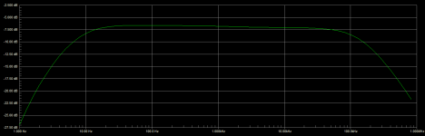
Here is your response with 7.5k load as in your schematic. And a second one with 75k load. Same shape in the HF but the gain goes up to 40dB and the sub bass roll off is shallow of course. You should not overload the output with less than ~28k load since it has 2.8k source impedance. You can alternatively shape the sub-bass roll off with a smaller value coupling capacitor either between stages or at the output.
Attachments
Hey Salas, thanks again for helping me out with simulating... How would you implement the sub bass roll off? Do i need it? I already tried a smaller coupling cap after the first stage but i had the feeling that this was no good idea, because of the very small signal the bass frequencies still have after the first stage.
What would happen if i drive the output coupling cap without the load like in the original pacific circuits?
What would happen if i drive the output coupling cap without the load like in the original pacific circuits?
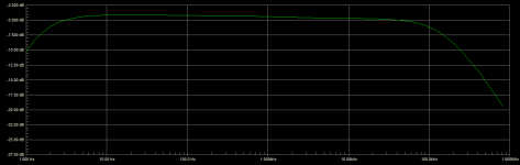
You need some sub bass roll off not to pass too much of the records eccentricity and some other low Hz resonances to the amp and speakers. You know, that excessive woofer pumping thing that can happen in some systems when playing records. That is why there was a phono subsonic filter in old Hi-Fi amplifiers.
As it is you can simply use 27k instead of 7.5k at the output. It will not stress the output stage while having some roll off when retaining the smooth overall response shape.
As it is you can simply use 27k instead of 7.5k at the output. It will not stress the output stage while having some roll off when retaining the smooth overall response shape.
Attachments
Hey Salas, thanks again for your explainations I just finished another version of this wonderful circuit. I cleaned up the signal routing, no crossing wires left I also cleaned up the grounding. I use only one Output cap for my capacitance multiplier, and this cap is mounted in the middle of my circuit where it provides VCC+ and at its negative leg i put my signal ground.
I also changed the load of the output coupling cap to 28k.
No hearable PSU noise anymore!
But when i put the needle on the non-turning record i can hear a bit of hum (when the volume of my amp is fully cranked up)
My Turntables cable is connected to the metal case of the preamp and leads further to my amp where it is connected to the earth lug of the case same way. Fiddling with this cable did not bring a change.
I am using a Technics 1200 MKII, my pacific preamp and a Sony TA-F461R (which tends to hum, also without stuff connected at the inputs).
Am I right with connecting my signal ground of the circuit to the negative leg of the output bypass cap of the capacitance multiplier? Is this my correct "0V-point"?
I just finished another version of this wonderful circuit. I cleaned up the signal routing, no crossing wires left I also cleaned up the grounding. I use only one Output cap for my capacitance multiplier, and this cap is mounted in the middle of my circuit where it provides VCC+ and at its negative leg i put my signal ground. I also changed the load of the output coupling cap to 28k.
No hearable PSU noise anymore!
But when i put the needle on the non-turning record i can hear a bit of hum (when the volume of my amp is fully cranked up)
My Turntables cable is connected to the metal case of the preamp and leads further to my amp where it is connected to the earth lug of the case same way. Fiddling with this cable did not bring a change.
I am using a Technics 1200 MKII, my pacific preamp and a Sony TA-F461R (which tends to hum, also without stuff connected at the inputs).
Am I right with connecting my signal ground of the circuit to the negative leg of the output bypass cap of the capacitance multiplier? Is this my correct "0V-point"?
Maybe the cart picks some little hum from the TT motor (when its an AC motor). If the little hum increases at different positions across the arm's arc while hanging above the record then its just about a hum field.
A bad place to use as zero reference is the reservoir capacitor's (-) just after the rectifier where the recombination currents return. Its a ripple infested point. So don't connect the multiplier's capacitors as a star to the first reservoir capacitor's (-) but keep them connected to it at the end of a longish zero line and their (-) should be a clean point to use as zero reference.
A bad place to use as zero reference is the reservoir capacitor's (-) just after the rectifier where the recombination currents return. Its a ripple infested point. So don't connect the multiplier's capacitors as a star to the first reservoir capacitor's (-) but keep them connected to it at the end of a longish zero line and their (-) should be a clean point to use as zero reference.
Okay, i think i have wired it in the right way. I dont have a rectifier, my power source line looks like this:
24 V Wallwart PSU --> LM317 Circuit with regular 1uF (tantalum) at the output --> capacitiy multiplier --> longish line --> 2200uF Output cap directly mounted on my preamp board. I Use the (-) of the 2200uF cap as my zero reference. Will post a pic of my current setup later.
The reason why i can hear the hum better is that all other noise levels went way down. I should wire the preamp to some other random amps in my house to firgure out if the hum depends on the amp, preamp or turntable.
Where should i connect the turntables "ground" wire? At my zero reference? Should i connect my metal cookie-box to some point on the circuit to achieve a better shielding?
okay, i did some days of listening and testing. I am not happy yet and will try to improve the output section again. I want to avoid building a buffer stage but i maybe will have to. But before that, I calculated a bit and thought about the output capacitator size and especially its load resistance in combination with the input resistance of my amp (which is unknown but expected to be between 10k and 47k, so i calculated 25k)
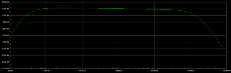
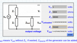
If we simplify things and calculate the output section of the preamp and the input impedance as a loaded voltage divider, i can see how bad the driving capabilitys of my circuit are (see picture 1).
With my highish preamp source impedance of 2k8 ohm and my output cap load resistance of 28k ohm and a 25k'ish input impedance of my amp, only 82% of the voltage arrives at the input of the amp. (picture 1)
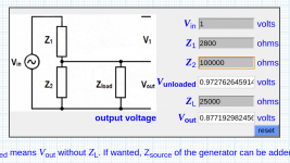
Fiddling around with the different values showed me that a first aid would be to put 100k instead of the 28k output coupling cap load resistor i use now. With an input impedance of 25k, 76% of the original signal will arrive at the amps input (picture 2)
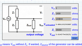
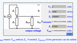
But the final conclusion is if i want better drive capability i need to lower my output impedance. To lower my output impedance i would have to replace the drain resistor of Q2 with 1400 Ohm (instead of 2800 Ohm).
I will lower my output coupling cap to .680 uF. I already checked that would be okay if change my circuit to match the scheme to the newest version ( picture 4 )
My question is: will my gain be the same when i use a jfet with an Id of 6.6 mA with a drain resistor of 1400 ohm compared to when i use and Id of 3.3 mA with a drain resistor of 2800 ohm?
second question: did you do your simulations of the circuit considering a reasonable load impedance of the amps input connected to the preamps output? like 10k, 25k or 47k?
Voltage divider - loaded and open-circuit dB calculator damping volts potentiometer circuit impedance damping pad decibel dB voltage attenuator impedance bridging matching - sengpielaudio Sengpiel Berlin
If we simplify things and calculate the output section of the preamp and the input impedance as a loaded voltage divider, i can see how bad the driving capabilitys of my circuit are (see picture 1).
With my highish preamp source impedance of 2k8 ohm and my output cap load resistance of 28k ohm and a 25k'ish input impedance of my amp, only 82% of the voltage arrives at the input of the amp. (picture 1)
Fiddling around with the different values showed me that a first aid would be to put 100k instead of the 28k output coupling cap load resistor i use now. With an input impedance of 25k, 76% of the original signal will arrive at the amps input (picture 2)
But the final conclusion is if i want better drive capability i need to lower my output impedance. To lower my output impedance i would have to replace the drain resistor of Q2 with 1400 Ohm (instead of 2800 Ohm).
I will lower my output coupling cap to .680 uF. I already checked that would be okay if change my circuit to match the scheme to the newest version ( picture 4 )
My question is: will my gain be the same when i use a jfet with an Id of 6.6 mA with a drain resistor of 1400 ohm compared to when i use and Id of 3.3 mA with a drain resistor of 2800 ohm?
second question: did you do your simulations of the circuit considering a reasonable load impedance of the amps input connected to the preamps output? like 10k, 25k or 47k?
Voltage divider - loaded and open-circuit dB calculator damping volts potentiometer circuit impedance damping pad decibel dB voltage attenuator impedance bridging matching - sengpielaudio Sengpiel Berlin
Attachments
Little update: after some more testing i located the source oft the hum when my dl-110 sits on the record, but the platter is not turning. It is the transformer oft my 1200 which seems to create a very small vibration at 50hz. The Motor itself works with DC not AC.
So the next big project is to move the transformer out oft the technics case and put it in a external box.
So my next bigger Project will be
So the next big project is to move the transformer out oft the technics case and put it in a external box.
So my next bigger Project will be
I guess the trafo has mechanic vibrations, not electromagnetic hum. Because the hum is only present when i put the needle in the record whilst the platter is NOT moving. The hum seems to be induced in a mechanical way. If i just place the needle next to the platter (using the needle protection plastic as a stand) there is no hum at all. Thats why i dont believe that electromagnetic fields are causing the hum in this case. The problem is very audible with low compliance carts. With Ortofon DJ Cart the hum signal is much loser, maybe because they are more "stiff"?
P.S.: i still love to play records with the preamp, despite wanting to optimise it... I am just so glad that the hum is not caused by the preamp circuit. Thanks for helping me a lot in that way.
P.S.: i still love to play records with the preamp, despite wanting to optimise it... I am just so glad that the hum is not caused by the preamp circuit. Thanks for helping me a lot in that way.
Last edited:
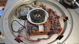
smps kills my mechanical hum problems...
After our latest reasonings i read a lot of threads about noisy technics 1200 mkII transformers and decided to install a simple SMPS instead of it. I removed the internal transformer and put a Meanwell RS-15-24 inside the deck. That totally solved my hum problem that i had with the needle sitting on the non-rotating record groove. Now it is dead-quiet.
I will improve the implementation of the SMPS further, but for now i am pretty satisfied. Costs: $ 10,- for the ready-made SMPS. Effect: much less noise, hearable better soundstage, more defined and clear bass then before. Biggest bang for the buck i have seen yet.
Next step is to re-adjust the rumble filter of the phono stage to reduce the motorboating-effects...
Attachments

Wow so much great information on refining the Le Pacific phonostage.
I would like to build the revised circuit Salas shared in post # 49, but my jfets have an idss of 5.6. Could I still use this circuit? Should I change the bias resistors? Would this change the gain?
Thanks in advance.
I would like to build the revised circuit Salas shared in post # 49, but my jfets have an idss of 5.6. Could I still use this circuit? Should I change the bias resistors? Would this change the gain?
Thanks in advance.
I guess you could do it, but if you use the exact part values given by Salas in post 49 you will end up turning the bias resistor oft the second stage to 5-10 ohms max. I would suggest to use a simple lm317 variable voltage regulator to tune the Vcc until the VDS oft the second jfet stage is 1/2 of the supply voltage that reaches your circuit.
With the idss of 0.0056A, no sources resistor and the drain resistor of 1.5k at the second jfet, you will end up tuning your Vcc to around 17 volt.
Use a 50R trimmer for the source resistance and tune between 0R and 20R to figure out what fits best.
Add the capacitance multiplier that Salas advised me a few pages ago to clean your supply voltage from noise.
- Status
- This old topic is closed. If you want to reopen this topic, contact a moderator using the "Report Post" button.
- Home
- Source & Line
- Analogue Source
- Pacific RIAA phono pre: failure!