Yesterday I did not manage to do this, I will try to do it this evening")
Did you found time so far?
Hello all
I posted earlier (#472) measurement of some Fairchild BC337s.
You will find below measurements of BC337s manufactured by ON Semi, purchased from Digikey Canada in early December. Part number BC337-040GOS-ND, Date code April 2010, made in China. Again the circuit used is as shown in Post #72.
Results:
HFE #
>465 20
460-465 8
455-460 6
450-455 10
445-450 1
440-445 9
435-440 8
430-435 12
425-430 19
420-425 6
415-420 15
410-415 19
405-410 21
400-405 24
395-400 29
<395 36
These are lower values than the Fairchild devices.
BC227s measurements are next. ON Semi first, then Fairchild.
Pierre
Did you found time so far?
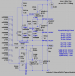
Yes I did, and I do not know what to say
The attached picture has your numbers in it, it is fed from the voltage you gave, it generates the output voltage you measured. Then I added your measured voltages (test points, Vbe’s and Vak’s of the LED’s) and I sat back and watched
And my conclusion is, I DO NOT UNDERSTAND IT
There are no Si based transistors with a Vbe of 0.2V (as calculated) or 347mV (as you measured).
The PSU is operating as expected, outputting +18.23V and -18.21V, the current sources seem to work. Now we need some smart person to figure it out.
Attachments
Hopefully this will spur on some responses.
An externally hosted image should be here but it was not working when we last tested it.
All soldered up just wondering about how to wire up the loading resistor? Am i right in thinking it just goes from signal to ground. If so can I place it at the input on the pcb
Looking good!! Yes, the input resistors can go on the second pair of input contacts, thats why they are there. They should be connected "floating" from that point, that means, do not connect the input resistor to GND at the resistors but only here.
That looks very good. So you have a Paradise R2.
Ah yes..... the final bug.... the PCB on the picture is R3 (as can be seen from the input offset adjustment trimpot) but the text on the PCB says R2... so sorry about the confusion.....
Yes I did, and I do not know what to say
The attached picture has your numbers in it, it is fed from the voltage you gave, it generates the output voltage you measured. Then I added your measured voltages (test points, Vbe’s and Vak’s of the LED’s) and I sat back and watched
And my conclusion is, I DO NOT UNDERSTAND IT
There are no Si based transistors with a Vbe of 0.2V (as calculated) or 347mV (as you measured).
The PSU is operating as expected, outputting +18.23V and -18.21V, the current sources seem to work. Now we need some smart person to figure it out.
Thats a good one... just spent 30min looking at the same picture, in wonder....
BTW, VBE of Q104 is -1.79V, not 1.79V. It should be fully off. Still, Q103 seems to be conducting, else there would be no output current. But it is doing something between open and short circuit, else V(TP103) would equal the input voltage.
@beetle:
Does this problem happen when you turn on the prereg voltage very quickly (e.g. plugging in a plug) or also when you ramp it slowly (with the voltage button of a lab supply)?
And, are you shure you have no solder joints on the bottom side where they are not supposed to be?
And, can you please check with a resistance meter between the collector tabs of all power transistors (when power is turned off, of course) to see if there is no short through the heatsink?
Hello Alfred,
hello FdW,
Power transistors are isolated. I had to to this as I mounted them to the sink with screws. The mosfets are in a plastic case so not needed here. But to make sure, I measured 6MOhm from GND to metalcase.
My soldering looks good. But to make extra sure, I'll wash the PCB in alcohol tomorrow.
At 21V both currents are 130mA.
24V: -138mA, +147mA
26V: -147mA, +161mA
28V: -151mA, +170mA
30V: -155mA, +178mA
Thanks for your help.
At 21V both currents are 130mA.
24V: -138mA, +147mA
26V: -147mA, +161mA
28V: -151mA, +170mA
30V: -155mA, +178mA
Thanks for your help.
Still hard to believe the current should very so much with input voltage, for both rails.... mine were rock solid (once the CCS was operating) and were not changing (but I am quoting this from memory, would have to re-check)
Do you know what... after friday it dosn't matter any more:
An externally hosted image should be here but it was not working when we last tested it.
BC337-40 as supplied with the group buy at both positions.
In my power amp I have a pair (one + one - 15V) of these PSU's running from 70V (finished a pair yesterday). The CCS current does not vary with input voltage (any way, this is prohibited by the leading CVS).
Mounting the wrong transistor (as Hessener noted) may make the reverse Vbe work as a zener and the CCS and CVS may conduct (this could also happen if the power transistors where wrongly mounted (I guess)).
But it is all a bit unlikely to lead to a functioning PSU.
I still cannot explain the hugely variant Vbe’s , I keep on watching.
Do you know what... after friday it dosn't matter any more:
An externally hosted image should be here but it was not working when we last tested it.
But it would be nice (for you) to enter Paradise before that time
and I am willing to help you escape disaster by doing so (enter Paradise before that time).In my power amp I have a pair (one + one - 15V) of these PSU's running from 70V (finished a pair yesterday). The CCS current does not vary with input voltage (any way, this is prohibited by the leading CVS).
Mounting the wrong transistor (as Hessener noted) may make the reverse Vbe work as a zener and the CCS and CVS may conduct (this could also happen if the power transistors where wrongly mounted (I guess)).
But it is all a bit unlikely to lead to a functioning PSU.
I still cannot explain the hugely variant Vbe’s , I keep on watching.
Frans, I was wondering if the transistors were somehow acting as a thyristor, triggering each other off... do you think that could be a possibility? Never heard of it though. And it might be due to very high (current) gain in the setup.....
But it would be nice (for you) to enter Paradise before that time
Subscribed to an alternative music magazine, and they had a review of the important events for the year 2012. And for dec 21, 2012, the note says: "The end of the world as we know it causes a lot of discomfort"
Frans, I was wondering if the transistors were somehow acting as a thyristor, triggering each other off... do you think that could be a possibility? Never heard of it though. And it might be due to very high (current) gain in the setup.....
May be (but unlikely). The numbers (measurements) are very unreal, and I cannot understand them. The gain of the power transistors can be diminished (lowered in importance) by lowering the resistors R100 and R103 (they could be lowered to 22 Ohms).
But as I do not understand what is happening, I am a bit afraid to advice a thing like that (it could be that doing experiments like this does more harm than good).
Subscribed to an alternative music magazine, and they had a review of the important events for the year 2012. And for dec 21, 2012, the note says: "The end of the world as we know it causes a lot of discomfort"
That's true
As I see it "The world as I know it ends every moment and a new one starts at the same moment".
Or, the multiverse is here today, was here yesterday, and will be here tomorow (and the day before and after).
- Home
- Source & Line
- Analogue Source
- Paradise Builders