No more J310 in my stock.... can I use J107 instead... seems to have comparable Idss but much higher Cdg.... ?!
Yes you can
") but change the resistor (from 3.3k) to 2.7k (the current set should be (about) 1mA).
but change the resistor (from 3.3k) to 2.7k (the current set should be (about) 1mA).Yes you can
Hi Frans,
this little secret will be part of the german translation of the building guide,
tanksalot !
Btw,
what happens if not ?
hi guys,
got 3 more questions in my head i hope you can help me with - i`m not that confident about those things
1) the Paradise R3 assambly guide shows a pic of the installeion on the last page - it looks like there are XLR connectors besides the RCA IN/OUT - is that right?
i thought the R3 does not deliver a balanced output - is this only an unbalanced XLR taken from the RCA output?
2) Input impedance selector - what is the best choice? thought about a rotary switch with 2 Pole/Deck x 6 Positions?? other suggenstions?
3) Load impedace resistors - i thought 10R, 47R, 100R, 249R, 475R, 1000R would be a good choice. am i missing something?
thank you guys for your support!
regards,
michael
Hi Michael,
1) yes thats what I did, I have XLR connectors on my turntable, so I wanted connectors to connect it to. Of course the inputs and outputs are unbalanced, the connectors are simply unbalanced XLR
2) Thats exactly what I did
3) same thing here. Dale RN65 worked fine for me
Hope that helps!
Hi Frans,
...what happens if not ?
If not what?
If not what?
(the current set should be (about) 1mA)
Hi Michael,
1) yes thats what I did, I have XLR connectors on my turntable, so I wanted connectors to connect it to. Of course the inputs and outputs are unbalanced, the connectors are simply unbalanced XLR
2) Thats exactly what I did
3) same thing here. Dale RN65 worked fine for me
Hope that helps!
Helps a lot, thank you Alfred!!!
Yes you can
Thank you Frans.
Can I also use J107 in the amp's output buffer ?
Thank you Frans.
Can I also use J107 in the amp's output buffer ?
I did that and it works fine, the "problem" being that there is a -1.5V offset now, since the J107 has a larger IDSS. That is no issue for circuit performance, just limits a little bit the headroom which is still very high...
But it is a compromise... I will keep searching for j310 then
Try the J109, at IDSS = 40mA (thats the center value for J310 but the lower datasheet limit for J109). That should be fine, as at these currents the threshold voltage impact is pretty big, so the devices will perform quite similar.
Show me (one more time) a full set of voltages test-points, Vin and Vout. Also would you measure all Vak(LED's) in the CVS and the CCS and, V(be) power and small signal transistors. It seems that the PSU is working but I want to know (at a philosophical level) why it is (as it is). This will make it easier to help other people.
P.s. The MJE's should be good, also the TIP's and the D44/D45's, but the D44/D45 where my first choice
Ok here we go:
TP101: 19.93V
TP102: 18.23V
TP103: 23.83V
TP104: 562mV
V(in)=29.88V@174mA
V(L110): 1.90V
V(L111): 1.90V
V(L112): 1.91V
V(BE Q101): 607mV
V(BE Q102): 347mV
V(BE Q103): 7.34V
V(BE Q104): 1.24V
TP201: -19.68V
TP202: -18.21V
TP203: -23.71V
TP204: -571mV
V(in)=-29.84V@151mA
Last edited:
If not what?
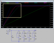
A picture tells more than a thousand words, so here is a picture.
The voltage (Vgs) of the mosfet is about 4V, the current that is (selected by me) wanted in the Jfet is 1mA. The picture shows resistor values for popular Jfet's to accomplice this (1mA). What can be seen is that, in fact, the J310 is the most marginal of the shown Jfet's (it is just capable of supplying the wanted 1mA).
Any of the Jfet's shown can be used (and I am sure there are many more) but you need to change the resistor value and indicated.
Attachments
Ok here we go:
TP101: 19.93V
TP102: 18.23V
TP103: 23.83V
TP104: 562mV
V(in)=29.88V@174mA
V(L110): 1.90V
V(L111): 1.90V
V(L112): 1.91V
V(BE Q101): 607mV
V(BE Q102): 347mV
V(BE Q103): 7.34V
V(BE Q104): 1.24V
TP201: -19.68V
TP202: -18.21V
TP203: -23.71V
TP204: -571mV
V(in)=-29.84V@151mA
I will, tonight, have a look at them. At first glance it seems the V(be Q102) is a bit low, and that this is debit of the current unbalance.
I am new to transistor matching so the question might be silly, but would a device such as the following be useful?
Found at Reichelt: ATLAS DCA55
Your feedback will be appreciated - thx.
dubai2000
checked it out - very nice. I am tempted to buy one myself.... It will do not only bipolar but also JFETs and other stuff....
In fact, matchign the gain devices makes a hell of a difference for audio amplifiers, as compared to just sticking in whatever comes out of the bag first. Many higher-performance (non-feedback) circuits really only work with selected / matched devices.
Watch only that the Atlas does shove much Ib with a CCS inside, so the reported Vbe will be more than usual in circuit. But if they match @ that condition they do follow with other bias states more or less. Good thing is it tests LEDS in a much more real life 3.5mA than the proverbial 1mA that meters do. Many don't even put out enough voltage to light an LED to start with. What Vf matches on my Atlas matches on my F87V too, but when looking to use them as voltage ref you need to know not only matching but Vf @ bias current too. Ah, and Atlas is a battery hog.
- Home
- Source & Line
- Analogue Source
- Paradise Builders