Small but important correction
Hello Icsaszar,
That is not correct. A straight line from the tone arm pivot to the stylus, passing through the center line of the cartridge, must be tangent to the RADIUS of the LP, not the groove.
The grooves cross the radius at a small angle which constantly changes, depending upon the pitch of the grooves (.002" to .011")
Sincerely,
Ralf
2. This can be fulfilled only if the pivot is always in line with the tangent of the actual groove.
Hello Icsaszar,
That is not correct. A straight line from the tone arm pivot to the stylus, passing through the center line of the cartridge, must be tangent to the RADIUS of the LP, not the groove.
The grooves cross the radius at a small angle which constantly changes, depending upon the pitch of the grooves (.002" to .011")
Sincerely,
Ralf
must be tangent to the RADIUS of the LP, not the groove.
Ralf
perpendicular to the radius?
Ray K
What will this prove unambiguously?I have an idea to possibly clear up any ambiguity wrt out of groove skate force testing.
A blank LP either chemically etched with a pattern corresponding to a 1khz mono signal, or a metal plate etched the same to press a blank LP.
It appears from investigations that you could etch any signal you could possibly need (in metal, so far).
Any critique why this won't work?
Ray K
The magnitude of the increase in skate force from a blank LP.What will this prove unambiguously?
Ray K
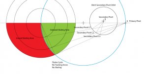
If stylus moves along Thales cycle, there are no skating and no tracking errors. In all other areas, both tracking errors and skating exist. Please see the drawing.
I call pivot A as primary pivot. A primary pivot can be a physical pivot or it can be a imaginary pivot. As long as there is only one primary pivot, stylus must move along Thales cycle in order to achieve free of skating and zero tracking errors. I call all other pivots, B, C1, C2 and C3 as secondary pivots.
If a tangential pivot tonearm is linear tracking, I am not going to discuss here.
If a tangential pivot tonearm makes curved tracking and has multiple primary pivots, the stylus doesn’t necessarily need to move along Thales cycle. As long as the cantilever is tangent to the radius of the LP, there will be no skating and no tracking errors.
Attachments
perpendicular to the radius?
Hello diyrayk,
You got me there! You are right of course.
Hello Icsaszar,
Are you reading this?
")
Sincerely,
Ralf
super10018,If stylus moves along Thales cycle, there are no skating and no tracking errors. In all other areas, both tracking errors and skating exist. Please see the drawing.
I call pivot A as primary pivot. A primary pivot can be a physical pivot or it can be a imaginary pivot. As long as there is only one primary pivot, stylus must move along Thales cycle in order to achieve free of skating and zero tracking errors. I call all other pivots, B, C1, C2 and C3 as secondary pivots.
If a tangential pivot tonearm is linear tracking, I am not going to discuss here.
If a tangential pivot tonearm makes curved tracking and has multiple primary pivots, the stylus doesn’t necessarily need to move along Thales cycle. As long as the cantilever is tangent to the radius of the LP, there will be no skating and no tracking errors.
I don't contest anything you say about tracking errors, but I disagree about skating. It is natural to want to assume that if tracking error is zero then so is skating, but this is not the case. Primary pivot A may very well serve as the virtual pivot that satisfies the math for zero tracking error. However, the drag force on the stylus acts on a real pivot, in this case a linkage comprised of pivots B and C. If the stylus drag force vector does not line up with pivot B, then the drag force will resolve into some component of skating force. You can have tangency and zero tracking error yet still have skating. The red and green zones in your drawing show regions of positive or negative tracking error, but don't correlate with skating characteristics.
Ray K
super10018,
I don't contest anything you say about tracking errors, but I disagree about skating. It is natural to want to assume that if tracking error is zero then so is skating, but this is not the case. Primary pivot A may very well serve as the virtual pivot that satisfies the math for zero tracking error. However, the drag force on the stylus acts on a real pivot, in this case a linkage comprised of pivots B and C. If the stylus drag force vector does not line up with pivot B, then the drag force will resolve into some component of skating force. You can have tangency and zero tracking error yet still have skating. The red and green zones in your drawing show regions of positive or negative tracking error, but don't correlate with skating characteristics.
Ray K
Ray,
You are right. Even before your post, I realized that my statement was not strict. I took Birch geometry to illustrate my so called secondary pivots. But I didn't mean there are no skating for arms based on Birch geometry as my drawing.
Jim
Ray is correct, irrespective of the geometry that the arm is based on. The key is to take secondary pivot B "out of the equation". If the (only) force vectors are congruent with the line: stylus - primary pivot A, and identical in length, there won't be any skating force(permanent tangential position a prerequisite).
Waaaay back in the thread, you can find a Thales based arm I built with a(n actual) thread maintaining the position of the headshell and providing a compensation force that diminishes with tracing radius becoming smaller. Ray will likely call this an antiskating mechanism(I have no problem with that, though it is an integral part of the design.
The LT is utilizes the above principle, but doesn't feature a single extra part(i.e. string, spring...) to achieve this.
All the best,
Frank
Waaaay back in the thread, you can find a Thales based arm I built with a(n actual) thread maintaining the position of the headshell and providing a compensation force that diminishes with tracing radius becoming smaller. Ray will likely call this an antiskating mechanism(I have no problem with that
, though it is an integral part of the design.The LT is utilizes the above principle, but doesn't feature a single extra part(i.e. string, spring...) to achieve this.
All the best,
Frank
Here are my additional comments.
Congruent with the line. Yes.
Identical in length. No. From A to C's, the distance can't be identical in order to meet Thales Theorem. In other words, they can't be identical to achieve zero skating and zero tracking errors. If you mean from blue line to C, yes. They are identical.
Jim
If the (only) force vectors are congruent with the line: stylus - primary pivot A, and identical in length, there won't be any skating force(permanent tangential position a prerequisite).
Congruent with the line. Yes.
Identical in length. No. From A to C's, the distance can't be identical in order to meet Thales Theorem. In other words, they can't be identical to achieve zero skating and zero tracking errors. If you mean from blue line to C, yes. They are identical.
Jim
Last edited:
That's what I meant to say: Stylus position = blue line.
So, to take B out, vector C-A and Vector C - blue line have to be of equal length. If B is fixed/rigid for any given moment in time(as it is in the serve-controlled Reed pivoted linear tracker), then there is no second vector.
Forgive me, the entire theoretical foundation has been discussed here at infinitum and frequent repetitions seem to deter, rather than encourage people from actually building something. I'll be back when it come to checking out practical implementations
Cheerio,
Frank
3DTOY PLT - how to do
attachnents
geometry (download the free program "Linkage 3. ")
STL mesh files of the individual parts, to be printed
bill of materials
wand - 6x5 mm tube (carbon or aluminum)
screws: 6 - 3x12 mm; 1 - 4x12 mm; 1 - 5x12 mm
grains: 2 - 3x4 mm steel
bearing's grains: 10 - 2,5x5mm brass (make a conical seat with a 2mm centerdrill)
ballpen tips: 10 - 2x10 mm refills
O-ring: 1 - 30x2mm
CW - 100 gr - 2mm lead shots
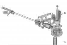
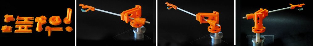
advice - try to get the best possible printing, with nozzle < 0.3 - A better finish is obtainable with SLA printing, or with boring post processing - but this unusual toyish appearence, for a tonearm with such sofisticated geometry (Birch-Dtut doublearm), is not so bad, imho.
Parts are designed with no clearance to get a tight fit, so deburring and adapting are needed. Pilot holes must be accurately reamed or threaded to size - this arm is all in his articulations, which is up to you.
disclaimer - this is not a kit, just a non-commercial project for lazy diyers. Mine works fine, smoothly and with no chattering, and the same must do yours, if you'll use a bit of your skill.
carlo
P.S a special thank to my friend's advices and patience, since printing takes much more time than making by hands.
"That's the printing, baby. The printing, and there's nothing you can do about it. nothing"
attachnents
geometry (download the free program "Linkage 3. ")
STL mesh files of the individual parts, to be printed
bill of materials
wand - 6x5 mm tube (carbon or aluminum)
screws: 6 - 3x12 mm; 1 - 4x12 mm; 1 - 5x12 mm
grains: 2 - 3x4 mm steel
bearing's grains: 10 - 2,5x5mm brass (make a conical seat with a 2mm centerdrill)
ballpen tips: 10 - 2x10 mm refills
O-ring: 1 - 30x2mm
CW - 100 gr - 2mm lead shots
advice - try to get the best possible printing, with nozzle < 0.3 - A better finish is obtainable with SLA printing, or with boring post processing - but this unusual toyish appearence, for a tonearm with such sofisticated geometry (Birch-Dtut doublearm), is not so bad, imho.
Parts are designed with no clearance to get a tight fit, so deburring and adapting are needed. Pilot holes must be accurately reamed or threaded to size - this arm is all in his articulations, which is up to you.
disclaimer - this is not a kit, just a non-commercial project for lazy diyers. Mine works fine, smoothly and with no chattering, and the same must do yours, if you'll use a bit of your skill.
carlo
P.S a special thank to my friend's advices and patience, since printing takes much more time than making by hands.
"That's the printing, baby. The printing, and there's nothing you can do about it. nothing"
Attachments
Last edited:
- Home
- Source & Line
- Analogue Source
- Angling for 90° - tangential pivot tonearms