
Just for curiosity, I have tested like you said other shunt regulator that I have build on the breadboard and tested with several capacitors, and I assure you that is very stable.
And it happens the same, added the 100nH in the simulation and the circuit start to oscillate, 100nH is a litle higher, normally the inductance is between 10nH.
But ofcourse , I only start designing the HEC shunt circuit today, It has to be built and tested in real life, there is room for improvements I am sure.
After the conversation with Keantoken, I was curious and decided to built the HEC shunt circuit in the breadboard... and it works and is very stable.
It is stable with only 22nf at the output. Tested with all kinds of capacitors.
Just to test the simulation made earlier , I made a inductance with 10 turns with 10mm diametre and put in serie with a 1000uf cap, and it keeps the stability.
This is the more stable of the shunts regulators that i made , and the reason is that the feedback loop is lower in this one.
Now I realy have to built a pcb for this.")
It is stable with only 22nf at the output. Tested with all kinds of capacitors.
Just to test the simulation made earlier , I made a inductance with 10 turns with 10mm diametre and put in serie with a 1000uf cap, and it keeps the stability.
This is the more stable of the shunts regulators that i made , and the reason is that the feedback loop is lower in this one.
Now I realy have to built a pcb for this.
If you have taken apart a breadboard you will see the sockets have significant surface area, adding internal capacitances which may change stability behavior. I believe you when you say it's stable, but time is the ultimate test.
It should be possible to make a regulator fast enough that the inductance of the output trace is enough to stabilize it. It could be this is what you have done. While this may prevent complete instability, it still does not eliminate the effect of amplifying RF resonances.
Perhaps if it is stable, you can reduce compensation? At which point then does it become unstable?
Last edited:
Sergio,, then we just need it at +/-12 V..
I will most likely use something like that, in the housekeeping for my power amp.
I will do that, and then I let you know. First need to do more test in this one.If you have taken apart a breadboard you will see the sockets have significant surface area, adding internal capacitances which may change stability behavior. I believe you when you say it's stable, but time is the ultimate test.
It should be possible to make a regulator fast enough that the inductance of the output trace is enough to stabilize it. It could be this is what you have done. While this may prevent complete instability, it still does not eliminate the effect of amplifying RF resonances.
Perhaps if it is stable, you can reduce compensation? At which point then does it become unstable?
Keantoken, normally (
) I don't do things by chance , I do them based in my previous experiences.But ofcourse the final test will be done when a pcb is made.
The regulator is very stable. It is even stable without output cap If you add a 47pf miller compensation cap
I try even without the compensation cap from the HEC loop.
This means that both loops gain can be futher increase . But I will not do that, as stability is the more important aspect of a regulator, at least for me.
Ok. made a test to try to measure the output impedance, I have injected 16,2mA/1khz rms in the output of the regulator with 20ma DC . The output impedance on the breadboard is between 100uR and 150uR , I was not expecting such low values in a breadboard, in a proper pcb will be lower.
Even with such a low output impedance, 16ma can create visible noises in the power supply rail, that is the reason that I want low output impedance.
Even with such a low output impedance, 16ma can create visible noises in the power supply rail, that is the reason that I want low output impedance.
Attachments
It should be possible to make a regulator fast enough that the inductance of the output trace is enough to stabilize it. It could be this is what you have done. While this may prevent complete instability, it still does not eliminate the effect of amplifying RF resonances.
?
I think I understand now,what is your concern.
Normally voltage regulators rely only in feedback to improve output impedance and PSRR. And a regulator with the caracteristics of my HEC shunt would need a feedback loop gain so large, that instability problems would arise.
But my design is different, as it uses two separeted loop´s one with regular feedback and the other with the Hawksford error correction (HEC), the HEC does not alter the loop gain of the feedback loop , so it does not create instability in the feedback loop.
I have made the feedback loop lower than i normaly do in this regulator , the , improvements are due to the use of HEC.
Dr. Malkolms hawksford create this wonderfull thing that we call hawksford error correction. As Joachim said, is very rare used in amplifiers, and I think I am the first to use in a voltage regulator.
I hope my explanation was clear enough.
__________________
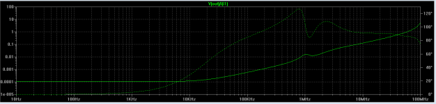
New test with a better common point, the output impedance with HEC is less than 20uR .
the first image is the output without the HEC loop ( to desactivate the HEC loop is only need to shunt a resistor ). 900uR
So the HEC loop improves things by 30dB.
the 2khz band is because the input signal is not a sin wave.
This demonstrates that such a low impedance is possible and practice.
the first image is the output without the HEC loop ( to desactivate the HEC loop is only need to shunt a resistor ). 900uR
So the HEC loop improves things by 30dB.
the 2khz band is because the input signal is not a sin wave.
This demonstrates that such a low impedance is possible and practice.
Attachments
Last edited:
Internal stability is not my concern. My concern is what happens when you connect it to a load.
Here is a revealing test. Inject a square wave from your signal generator into the output of the regulator through a cap and 330R resistor. Probe the output voltage and watch on the scope.
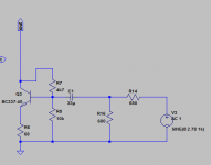
In simulation, output impedance at 100KHz can be reduced by a factor of 10 by making Q15 a BC560C.
Here is a revealing test. Inject a square wave from your signal generator into the output of the regulator through a cap and 330R resistor. Probe the output voltage and watch on the scope.
In simulation, output impedance at 100KHz can be reduced by a factor of 10 by making Q15 a BC560C.
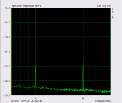
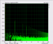
I use the circuit in post #9230 for injecting a square wave 200Hz and 2KHz of 0mA to 30mA in the output of the regulator and the signal at the output near the common point is barely visible at a scale of 2mv, there is no instability or spikes, My oscilloscope is a Fluke 100Mhz ,
Later on I have to test without the HEC loop and with a faster signal , but not now, its 105º F outsider , and is very Hot upstairs where I have my gear.
Using transistors with lower parasitic capacitances , expecially the base to collector , in nodes were the impedance is higher will increase the gain at higher frequencies.
I use only BC327/337 because is the only transistors in this moment that i have in smd version , and I want to made the test board with smd´s this week. But in future will try others , Do you know any transistor with very low parasitic capacitances and low VCE saturation?
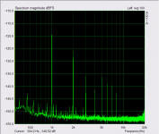
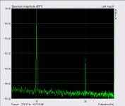
The image is the FFt of the 200Hz square at output. Next time will take fotos of the oscilloscope
Later on I have to test without the HEC loop and with a faster signal , but not now, its 105º F outsider
, and is very Hot upstairs where I have my gear. Using transistors with lower parasitic capacitances , expecially the base to collector , in nodes were the impedance is higher will increase the gain at higher frequencies.
I use only BC327/337 because is the only transistors in this moment that i have in smd version , and I want to made the test board with smd´s this week. But in future will try others , Do you know any transistor with very low parasitic capacitances and low VCE saturation?
The image is the FFt of the 200Hz square at output. Next time will take fotos of the oscilloscope
Attachments
Last edited: