They are right around the corner...
http://www.aquacut-solingen.de/
http://www.aquacut-solingen.de/
Last edited:
A little unit like this....could do the trick...can be cut with waterjet, glass blasted and anodized to a nice finish...would look good...")
Made of copper
(optional gold )
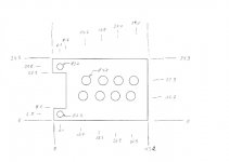
Here is a drawing of the dimensions. All in mm.
I have added two flanges where the thing may be fixed on the PCB. This would accept a 30x30mm heatsink on top of it quite nicely, aluminum or other (silver?). Not sure its needed though, some thermal grease to make good contact is probably enough.
Have measured a few different TO92's in the lab, and they all are between 4.58...4.63 in diameter where the belly is the widest ;-)
Attachments
Last edited:
Sorry Alfred,
by looking to the pictures of the Boards
i'm in doubt your drawing is correct.
5mm thick should be good ?
I'll go for CuSn bronce.
Should we do the mounting holes with M3 threads ?
Will there be screwholes in the final boards ?
Or shold the 24Q-legs be strong enuff ?
by looking to the pictures of the Boards
i'm in doubt your drawing is correct.
5mm thick should be good ?
I'll go for CuSn bronce.
Should we do the mounting holes with M3 threads ?
Will there be screwholes in the final boards ?
Or shold the 24Q-legs be strong enuff ?
I might be wrong 'cause technology is evolving each year but waterjet may be not up to the task...also money wise it may be cheaper to use CNC for these small details.
Anyone have any experience with cutting small details? I did only big stuff with waterjet, the last time I checked it was tricky to cut holes smaller than depth of the given alloy of such small diameter.
Anyone have any experience with cutting small details? I did only big stuff with waterjet, the last time I checked it was tricky to cut holes smaller than depth of the given alloy of such small diameter.
Sorry Alfred,
by looking to the pictures of the Boards
i'm in doubt your drawing is correct.
5mm thick should be good ?
I'll go for CuSn bronce.
Should we do the mounting holes with M3 threads ?
Will there be screwholes in the final boards ?
Or shold the 24Q-legs be strong enuff ?
Hi Benedetto, I have taken the dimensions from the PCB layout tool (in mil) and converted to mm, that is why there are some strange values. The drawing is not to scale, but the dimensions should be correct. The legs of the transistors are somewhat bendable so it doesnt have to be super-precise. I would prefer to not rely on the transistor legs to hold it, thats not good for reliability purposes (solder joints should not see mechanical stress, thats a no-no in power electronics).
5mm thickness should be good enough. Right now there are no screw-holes in the boards but they can be added. The places I suggested would fit with the wiring on the PCB, only groundplanes there. Threads in the holes would be great, and with 5mm there should be enough metal for good holding.
Copper/brass/bronze would be very fine materials. I don't fancy aluminium for heat-sinks, as it is para-magnetic. profound difference in sound where aluminium is not used. I know this here is small currents compared to an output-stage of an power amplifier.. but anyway
In my opinion it would not be a heat sink, but a ‘heat spreader’ with ‘high thermal capacity’. The point is that the heat is spread over all components and this will make them all 'behave' in sink. The thermal capacity is used to make sure that small drafts (or otherwise) cannot cool a single component, the draft needs to cool the 'thermal capacity device', as it is holding lots of (micro)BTU's it will not be easy (at the least it will not instantly cool) to cool, that is why you need that large thermal capacity.
BTU = http://nl.wikipedia.org/wiki/British_thermal_unit
BTU = http://en.wikipedia.org/wiki/British_thermal_unit
Last edited:
First Hesener, Frans, MiiB and all that have contributed with bigger and smaller things :
Thank you very much ! From design to working sample we did this in two month !
I am particular happy that the Paradise is " practically noise free and very clear sounding".
The transistors we use are not especially designed for MC input stages and nearly 40 years
old. So here we have prove of mind over matter.
Hesener, you could do me a favour : Adjust both the FPS and the Paradise with your volume control for the same gain. Then put your ear on the speaker at high volume, not playing a record of cause. How can you describe the sound of the noise ? Is there flicker and popcorn noise ? Does is sound like wind or running water or does is have a particular tonal balance ? How does the noise in the bass sound ? Does the Paradise have less noise in the bass ?
That the tonal balance is similar to the FPS is a good sign too. The FPS is dead accurate,
plus-minus 0.1dB, proven in simulation and measurement.
In fact i have found out that a phono stage with Fets at the input can have a slight elegant tone and a BJT is a bit more punchy and "matter of fact". We have to consider that the sound of the Paradise may change, i hope for the better, after run in.
Thax A.
Next week we'll get a pair or two protos.
CNC-milled.
Very cool! Happy to try them any time.
Hesener, you could do me a favour
Will do that tonight. Interesting experiment!
Hesener, i have done some experiments with DC offset and have published them here.
So far my conclusion is that 0.5mV into the Titan i is my perception theshold but that has to be put under scrutiny ones more. I have good hearing and a great system but it is dependent on my mood and other things. On some days i can identify very small problems and on some days i can not.
When i put in a lot more ( -20mV in one experiment ), distortion goes up a lot, uneven more the even. I will publish that graph ones more for reference.
I have not identified a distortion null yet but there is a tendency that this happens with Zero DC offset when the cartridge is adjusted correctly. I have adjusted the Titan meticulously with microscope and test tones from a DIN record, including intermodulation distortion, tracking ability, crosstalk, channel matching, down pressure, VTA, Azimuth, overhang, Zenith etc. I cleaned the test record and the needle wet before measurements.
Also you have to consider that the adjustment has to be done with a phono stage in place that may have offset to begin with so you see the effect of the whole lumped elements. Because you can view the DC offset as pushing out the coils somewhat from the rest position, this can be adjusted by changing the down pressure or putting an opposite DC in although both measures may have a different resulting spectrum.
If a distortion null can be achieved with a phono stage that has Zero DC offset plus a perfectly aligned cartridge and then unbalancing the stage i can not say at the moment but i check that out.
Hi Frans;
Al:204W/mxK
Gold:310W/mxK
Copper:384W/mxK
Silver:407W/mxK
I do prefer Copper anyway.
Check these out:
Thermal Properties of Metals, Conductivity, Thermal Expansion, Specific Heat - Engineers Edge
Metals - Specific Heats
Thermal Conductivity of Metals
Heat capacity - Wikipedia, the free encyclopedia
Thermal conductivity - Wikipedia, the free encyclopedia
P.s. I like copper too, it has a nice color
Last edited:
When i look at the plot more carefully i would say that all harmonics go up the same proportionally so there is no tendency that uneven ones grow more in proportion.
This measurement was not done on the same channel and it was a prototype from the waste bin so noise artifacts look different. You could also conclude that one channel has more
"jitter" that produces strong side lines around the 1kHz test frequency.
This measurement was not done on the same channel and it was a prototype from the waste bin so noise artifacts look different. You could also conclude that one channel has more
"jitter" that produces strong side lines around the 1kHz test frequency.
Attachments
I got an offer from Jahre in this case :Richard Jahre GmbH: Bauform 48