I did not know these could stand such high currents (Vishay)
Not constant though. Peak

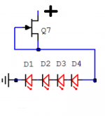
Here is something for you guys to chew on. The 4 LEDs are connected after the k117 (Idss 3,32) as in the circuit. All 4 LEDs measure over 2 Vdrop, some over 2,1 V measured the traditional way with a 9 V battery and 1 k resistor. In the circuit I cant get over 7,72 alltogether. If I use LEDs that measures lower with 9v/1K I get lower results in circuit.
Drain-source measures some 38,5, drain-gate some 39,0.
Drain-source measures some 38,5, drain-gate some 39,0.
Attachments
If I throw in a higher (Idss 3,60 SK117) it climbes upwards to 7,76, Idss 3,8 7,78 V, Idss 4,0 7,80 Vdrop over the quad.
Got one LED out to control. It dropped 2,14 V (one of the highest red 3 mm I had) and it dropped 6,82 over the 1 k resistor (6,82 mA). 6,82+2,14=8,96, battery running low.
Got one LED out to control. It dropped 2,14 V (one of the highest red 3 mm I had) and it dropped 6,82 over the 1 k resistor (6,82 mA). 6,82+2,14=8,96, battery running low.
Last edited:
Same string of 4 LEDs combined with 18,7 volts feed and 1 k resistor gives 8,4 V over the LEDs and 10,3 over 1 k.
With 2K2 resistor it has 7,8 Vdrop over LEDs and 10,9 over 2k2 (4,95 mA)
So, to even get those LEDs to drop the specified 7,75 V one has to go up in Idss to 3,9-4,0 mA.
Ergo: Few if any 3 mm red leds drop 7,75/4=1,94 volts at such low current (Idss) as 3-3,5.
Can that be the conclusion?
For 7,75 at Idss 3,3 I need to combine with a green.
Last edited:
The jFET acts as a CCS. It supplies the string of Vref with a nearly constant current.
Two factors influence the "goodness/badness" of the CCS: temperature and supply voltage.
The Vref voltage is "set" by the current through the semiconductors.
If the current is fixed, there is ONLY one other factor that changes the Vref: temperature.
Thus the Vref and it's regulated current supply is affected by supply voltage and temperature.
Keep the temperature rise low and then the total RANGE of temperature is lower.
Keep the supply voltage nearly constant and the range of supply voltage is also low.
Combine these two precautions and the Vref hardly changes voltage once the internal temperature has stabilised.
BUT
run the internal temperature of the case very high due to excessive dissipation of all the other components and you will get Vref drift. That drift (due to high Ta) will vary with draughts due to open windows/doors/people walking past.
Last edited:
The 4 Leds string and Q7 feed off about 17VDC in the FSP circuit.
Perfect. Ill find suitable SK117 tomorrow 4-5 mA and set up a string with them on 2*9 V.
The 4 Leds string and Q7 feed off about 17VDC in the FSP circuit.
So if B+ is 35 V then R15 3K3 must drop 35-17=18V and so the Idss of the FET must be 18V/3K3= 5,4 mA. Correct?
Or does Q3 take current thru base?
Last edited:
So if B+ is 35 V then R15 3K3 must drop 35-17=18V and so the Idss of the FET must be 18V/3K3= 5,4 mA. Correct?
Or does Q3 take current thru base?
Correct for those figures. Q3 takes 1.8mA/hfe through its base i.e. a drop in the bucket.
Though its not ending always at 35V Rail+ because of different needs between sensitivity builds and first stage JFETS Idss used, usually lower Rail+, but there about.
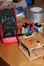
It is also the method. Using 10 ohm for measuring small current fets for example did not work for me. I have to use 100 ohm for the GRs. BLs can do with 10 but I think Ill stick with 100.
I use Vishay 100 ohm 0,1 %
I use Vishay 100 ohm 0,1 %
I took my box of cheap metal film 100 ohms and measured until I got a 100,0 ohm and then I use the same multimeter for measuring Vdrop.
Some times if the link between G+S is not very short and there are long leads from the battery biasing the JFET under measurement, the very high gain & high capacitance ones like the 369 can oscillate. They show less IDSS when that happens. You may see a sudden small drop on the battery or other PSU DC voltage if monitoring it. That's a sign it went off. I had mentioned that few times before.
Hi,
Finish the boards and power up today, some problems.
I can't get the +Rail and ground to be anywhere near 34-37V, I only get around 26-27V also tp1-tp2 is 7.4V for both channels. The input voltage is 51V. I am using r3x=6.2KOhms and r6x=33R. Should I increase r3X to around 10K or I'm doing something wrong?
Thank
CS
I use 500mm long croc clip leads for rough batching of jFET Idss.Some times if the link between G+S is not very short and there are long leads from the battery biasing the JFET under measurement, the very high gain & high capacitance ones like the 369 can oscillate. They show less IDSS when that happens. You may see a sudden small drop on the battery or other PSU DC voltage if monitoring it. That's a sign it went off. I had mentioned that few times before.
Never had a problem with instability.
Clip the G+S legs together with a croc clip. Other end goes to -ve of lab supply.
croc clip to D leg, other end goes to either 1r0, or 10r, or 100r, or 1k0, in the lab supply +ve.
The DMM voltmeter is clipped across the current measuring resistor.
adjust the lab supply to read the 10Vds+the voltmeter reading.
eg.
if the voltmeter across the 10r reads 0.023V then adjust the supply to read 10.02V.
Silly !
Select the 100r as the current reading resistor. Voltmeter reads 0.228V.
Adjust the supply to 10.228V. Better than using 10r. The Idss ~ 2.28mA
Last edited:
- Home
- Source & Line
- Analogue Source
- Simplistic NJFET RIAA