Cute assembly! You need to box it first and ground the box to the PSU 0 to really know your hum. Ground the signal cables shields to input and output 0 points too. Now there is a long test loop in the open. I don't see a spread of hum related harmonic noise high spikes though and that is a good start. In what section you use 5 leds in the reg and why?
Better use simple coax signal cable if you got any. Now I see two wires and a non grounded shield. Why you had to use 5 leds in the regulator? Is it in the CCS section? 3-4 are enough in the CCS section unless you don't have low value current set resistors handy. What version of the shunt reg is it?
I think I have those skinny gray-white coax somewhere, will put it to service here. Also I have tried to ground the shield on the board side, it did cut some mV. Shields are soldered both to RCA's
Sorry I forgot which version of your reg, but it is the same schematic as Quang Hao for their DAC supply, if you think this one is not good enough I'll go with yours as in PDF at post #1
Sorry I forgot which version of your reg, but it is the same schematic as Quang Hao for their DAC supply, if you think this one is not good enough I'll go with yours as in PDF at post #1
Its from same V1 family what you got. Good enough for MM phono, no worries.
How many Volt B+ you set? What is the voltage from second stage JFET drain to ground, and from output buffer top JFET drain to ground? Asking to see if you did the modification correctly. You put an RC filter for the B1 style buffer between B+ as in folded MC phonos schematics? Or is it the source resistor PDF buffer?
Its needed to keep dissipation balanced and the gate excess noise low in the buffer FETS beyond doing some extra filtering.
Try another test pass with same software, non-boxed but with your other cables. Use an LPAD 10K series/100 Ohm to ground between the signal generator and phono. Set and measure 300mV RMS sinewave on the gen out. That will bring 3mV to the phono with a much cleaner generator noise floor. Take a picture from that result and post it here if you may.
B+ is 28V. Will measure voltages later and report back. I'm looking for a nice box of tin can here at home. The buffer is the one with source resistor if I'm correct, no folded MC for sure, I'll save this page as not to miss your advice while offline ") , good idea that LPAD, quite difficult to give 4mV out of my lap top, thanks
, good idea that LPAD, quite difficult to give 4mV out of my lap top, thanks
, good idea that LPAD, quite difficult to give 4mV out of my lap top, thankshi Salas, here are the measurements, component values is not exactly similar to PDF, I'm using what's available, jfets idss are various and not final
R2 100R
R6 50R
R10 5K2
Q4 BC550B
B+ 28V
Q1 drain to ground 7.25V idss 8.53
Q2 d to gnd 11V idss 7.95
Q3 d to gnd 19.3V idss 8.57
Q5 d to gnd 19.3V
Q5 s to gnd 7.86V
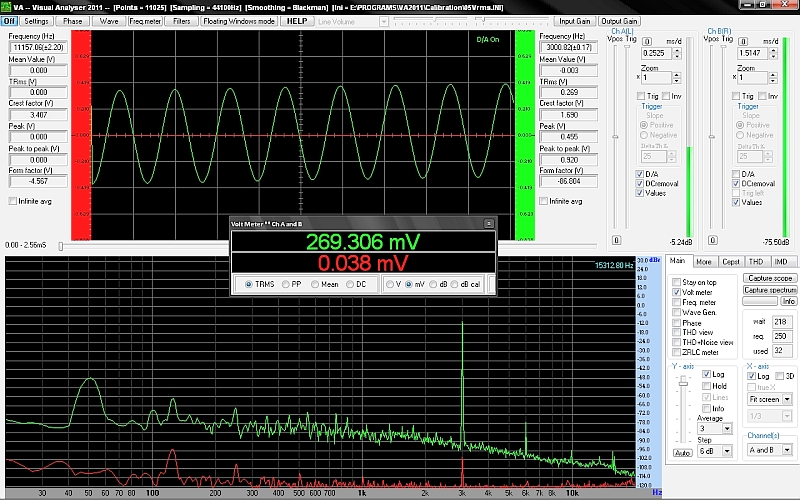
did coax measurement, bit jumpier than old wire but in general lower hum, twisting them helps, here are the pics. VA shot old cable is here


I've found a nice tin can, waiting to be drilled. Thanks Salas
R2 100R
R6 50R
R10 5K2
Q4 BC550B
B+ 28V
Q1 drain to ground 7.25V idss 8.53
Q2 d to gnd 11V idss 7.95
Q3 d to gnd 19.3V idss 8.57
Q5 d to gnd 19.3V
Q5 s to gnd 7.86V
did coax measurement, bit jumpier than old wire but in general lower hum, twisting them helps, here are the pics. VA shot old cable is here
I've found a nice tin can, waiting to be drilled. Thanks Salas
much better
hi Andrew, green is left channel, riaa output, red is unconnected, it is self noise of laptop. Helps me a lot this Visual Analyser.
very good news today. tin can ready, noise goes down, heard via headphone ampy faint hiss at normal level. Now I can match both channel.
Measuring with LPAD shows improvement, thank you Salas for your help
- Home
- Source & Line
- Analogue Source
- Simplistic NJFET RIAA