Hi Guys,
Just trying to find out if this board is for an improved version of the Simplistic RIAA or the original design. Reviewed the past 50 pages and seems a lot of different values are discussed for improvements. Is the PS included? What is BiB? Bigger is Better? Will the PCB be made public?
Thanks,
V~
This is a PCB, it is made for giving the project a practical side for more users beyond the highly custom p2p expert builds we practiced. PCB has the 1.1 smack to the phono, no wires its a plus.
The folded with the 1.1 are a good combo.
Just trying to find out if this board is for an improved version of the Simplistic RIAA or the original design. Reviewed the past 50 pages and seems a lot of different values are discussed for improvements. Is the PS included? What is BiB? Bigger is Better? Will the PCB be made public?
Thanks,
V~
Last edited:
Its the improved latest version with folded cascode input stage and integrated SSLV1.1 supply. It will go public as soon as it gets boxed up and passing proper final tests. In its final PCB revision it will have an assembly manual and BOM.
P.S. BIB is the 1.1 reg's nickname for "back in black". Comes from it got issued as a standalone regulator in black boards after a lengthy period of hot-rod double sided blue DCB1 issues, when the single sided originals used to be black.
P.S. BIB is the 1.1 reg's nickname for "back in black". Comes from it got issued as a standalone regulator in black boards after a lengthy period of hot-rod double sided blue DCB1 issues, when the single sided originals used to be black.
Its the improved latest version with folded cascode input stage and integrated SSLV1.1 supply. It will go public as soon as it gets boxed up and passing proper final tests. In its final PCB revision it will have an assembly manual and BOM.
Just to check I've read the past few pages correctly, this new PCB for the folded cascade input version will initially be MC only? Hoping I can adjust it for use wth my Shure V15V at some point
")
John
The 63dB test config took 5.1mV RMS or 14.433mV PK-PK @ 1kHZ input before clip. This is +26.2dB from a nominal 0.25mV RMS LOMC which is suitable for. If made with one K369BL instead of two, the gain will be 57-58dB and it will retain the headroom for normal MC 0.5mV. Those are almost standard matches in the majority of ready made phono stages.
The normal MC config in p2p assembly has been playing for long now with a Clearaudio Goldfinger Signature at a friend's which is near 1mV nominal with no reported clipping on 45RPM heavy cuts or any particular tick n' pop excitation.
It will have to retain such margins for MM also to be practical, but this kind of input stage is gainy. I will have to try out some modeling to see if it can bias the input stage for higher voltage midpoint and less current suitable for an MM. But with no adverse effects.
If I will succeed I will certainly let you know and I will include such an example in the guide. I can only discuss 2-3 popular use examples with specific IDSS in a forthcoming guide though.
In general when having the correct architecture well transferred on a versatile PCB, any special manipulation like using different available IDSS & Ygfs JFETs or targeting a specific gain is possible within reason, but it takes some JFET biasing expertise to manipulate the resistors and possibly the B+ level. Rcruz had published a very handy calc sheet for such. He uses a Denon DL160 HMC on the normal MC config even.
Yet we would like the levels and distortion to be always in best balance match.
Still, lets not jump the gun and make sure the proto behaves well after boxed up and connected to a real hi-fi rig. Each revision to the board means full retooling charges from the fab house.
Tea-Bag Mike does a beta assembly and he will be having boxes much sooner than me, lets see what his finished assembly situation will reveal soon.
Still, lets not jump the gun
Now I just carried 600 kg vinyls just for this
Now I just carried 600 kg vinyls just for this
No problem, you are a durable Swede. Probably equipped with a red vinyl cape for festive first listening occasions even.
An externally hosted image should be here but it was not working when we last tested it.
post9835
Does this parameter make any difference, significant or minor, in the performance of the pre?
The A970 shows a significantly higher Early voltage.BC560C Fairchild to the left at hfe 630. 2SA970BL
Does this parameter make any difference, significant or minor, in the performance of the pre?
Theoretically it is better to have higher Early for less THD but I don't know if it will be significant in practice at those signal levels. The Fairchild BC560C comes in high Hfe on the other hand which is desirable for less base modulation. So I designed in both options since it is easy so to can compare at a point for FFT when a build will be complete and final or find some subjective clue even.
Success!
I´ve had a few exams the last weeks, so I (literally) put all the diy gear under the bed for some time. When i fired the riia up again today and patiently fine tuned the psu, the test points were ok on both channels. Then I got sick of measuring and soldered on some connections to see if any sound came through. It sounds amazing! Sadly its night here, so I can only listen at very low levels. Still I can hear a lot of new details, and the bass is really coming through.
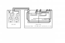
I´m also surprised by the lack of hum. Ok, it hums quite a lot when I turn up the volume, but I think its the same I already have from rf pick up due to long unshielded wires from the turntable. When I build a box for this, I need to connect the tone arm earth to the box, right? How about the signal earth?
Thank you Salas! This is really promising. I´ll probably rave some more tomorrow.
Because its double mono you can up slightly that channel's PSU until it gets there. Is there same mV drop on all source to ground resistors for both channels input stage Jfets? This small difference should be either you got a bit stronger one there or its PSU is bit lower. Or leds bit higher.
I´ve had a few exams the last weeks, so I (literally) put all the diy gear under the bed for some time. When i fired the riia up again today and patiently fine tuned the psu, the test points were ok on both channels. Then I got sick of measuring and soldered on some connections to see if any sound came through. It sounds amazing! Sadly its night here, so I can only listen at very low levels. Still I can hear a lot of new details, and the bass is really coming through.
I´m also surprised by the lack of hum. Ok, it hums quite a lot when I turn up the volume, but I think its the same I already have from rf pick up due to long unshielded wires from the turntable. When I build a box for this, I need to connect the tone arm earth to the box, right? How about the signal earth?
Thank you Salas! This is really promising. I´ll probably rave some more tomorrow.
Once again the importance of cart load strikes.... Searching for a low cost, wirewound pot to replace the expensive vishay metal bulk trimers I am fond of, I found this 534-5,0K - Präzisionspoti. 10 Gänge, 5,0 K-Ohm bei reichelt elektronik
An affordable precision 10k pot multiturn .... orderd two and today I implemented them and guess what... detail... loads of detail... bass precision and attack... outstanding.
An affordable precision 10k pot multiturn .... orderd two and today I implemented them and guess what... detail... loads of detail... bass precision and attack... outstanding.
Hi Salas... just found this strange schematic of the Sasa Cokic riaa where he loads the input tube with a riaa filter.... Would you please excuse the off topic and comment on the possibilities ?
I guess we have variable gain according to riaa slope.... is it a good idea ?
6moons audio reviews: DIY Sasa Cokic RIAA
I guess we have variable gain according to riaa slope.... is it a good idea ?
6moons audio reviews: DIY Sasa Cokic RIAA
What material is the resistive element in the precision Vishay pot? Wirewound?
Loading Riaa on upper side you may see in SRPP like with Nikitin solid state phonos. Not that unrelated to an anode Riaa on a pentode. Well, high impedance on one hand adds more noise and EMI susceptibility, also not so good in driving the second stage, but results to smaller capacitors physically on the other. Maybe the noise performance of the pentode as an input element already sets an SNR limit that preserving the head amp gain is preferable in a certain design. For headroom with MM and relying on a high ratio SUT for MC. Only the designer can give the whole story of his choices in reference to a concept he had.
Loading Riaa on upper side you may see in SRPP like with Nikitin solid state phonos. Not that unrelated to an anode Riaa on a pentode. Well, high impedance on one hand adds more noise and EMI susceptibility, also not so good in driving the second stage, but results to smaller capacitors physically on the other. Maybe the noise performance of the pentode as an input element already sets an SNR limit that preserving the head amp gain is preferable in a certain design. For headroom with MM and relying on a high ratio SUT for MC. Only the designer can give the whole story of his choices in reference to a concept he had.
- Home
- Source & Line
- Analogue Source
- Simplistic NJFET RIAA