I just bought a Tascam 58 8 track to experiment with... but that's certainly for another thread (sorry about all this nonsense Salas).
Google just taught me about Fi Audio... I guess you mean this one.
I'm working through some unusual chassis designs myself as this is probably what I'd be best at and also an area that I see is usually lacking in DIY builds. Cake tins are quaint and all, but if you are going to claim that something is as good as a $$$ unit, it should sorta look like it. Peter Daniels is on to it. Something that makes artistic sounds should look artistic to complete the picture.
Anyway, Salas, your Simplistic is great and I look forward to hearing the Itch. Maybe one day they will both make it into the kick-a$$ DJ console I'm working on (slowly).
Tani.
Hi Tani
I'm sure chassis design is a cool topic for any build thread.
Don Garber def. turns chassis design on it's head.
The constants, such as sheilding etc. remain the same, but plenty of scope is there for leftfield configurations.
My chassis are now (pre Don Garber) always built out of scrap & very leftfield parts, but adhering to good electrical principles.
Sometimes recycled material can yield a result which would otherwise be unexpected.
Obviously it must sound good, but if it looks cool it's a bonus.
Cheers
Simon
Power supplies
I am gathering parts for the 1.2R shunt and the pre-shunt filter.
A while back, SGregory spelled out his filter, no schematic. I made a schematic of it, attached. How does it look? SGregory, care to comment? Does one need that many uF's to adequately pre-filter?!?
As for the shunt, I hear C1 (4.7uF) quality is critical; C3 less so. I have 2 Wima MKP 4.7uF's. But as they are 400v, I was hoping to save them for valve use. Would good PIO's be OK instead?
-Kent
Attachments
Its essentially flat there with 33nF or 47nF too and you cut more around disc warp. Just test your 47n. You will find even 22n FT-1 very much passable with your now output caps and preamp load I believe with the real bass that is actually to be found in most records.
Thanks for the input Nick, I have to take a compromise point because my loudspeakers can't go well till 50-60Hz but my headphones go till 12Hz so I will follow your advice & first I will try with 47nF to see what's happen.
The rCLcLC PSU would work pretty well feeding straight into a the RIAA stage. You have ~25mF and two inductors in there for good ripple and interference attenuation.for the 1.2R shunt and the pre-shunt filter..........I made a schematic of it, attached. How does it look?
You are going to use a Shunt regulator between the PSU and the RIAA. I think you can cut back significantly on the cost/bulk of the PSU.
That little 1nF in the middle seems a nice touch. Another (or bigger) across the secondary and across the primary might give even more attenuation.
Sorry for more questions...
Are ordinary metal film resistors fine to use? I've got a good collection of the pale blue 1% types.
It looks like I can use 1/2 watt for all except for R1, which I will use a 1W resistor.
Cheers- Kent
Yes ordinary MF 1% are fine. R1 1W.
You see, never say never.
 BTW USA teflon caps 200VDC are far better than russian teflon caps 600VDC
")
USA in capitals and Russian starting with lower case ! Why?USA teflon caps 200VDC are far better than russian teflon caps 600VDC
On which parameters are you basing your conclusion?
I'll re-write that sentence to get the meaning over to you.
On which parameters are you basing your erroneous conclusion?
In many Latin based languages (including Italian and I think even Spanish) the capital is not requested in this case. English is different.USA in capitals and Russian starting with lower case ! Why?
Unless you know the English rule, you might be wrong. Merlin/Felipe and me are trying to write/read English, but we aren't motherlanguage.
USA is an acronym.
USA in capitals and Russian starting with lower case ! Why?
On which parameters are you basing your conclusion?
I'll re-write that sentence to get the meaning over to you.
On which parameters are you basing your erroneous conclusion?
In my language the country is with higher case but the people leaving in the country is with lower case.
Cap tight rolled one than other, room acoustic, HD600 give a lot of lows, speakers, human hear, etc.
If it's erroneus I can live with it
matching Jfet Idss and Vp tolerance
Hi folks-
I'm in the process of measuring Vp on all my 2SK170's. Doing the 9mA Idss batch at present. Vp's seem to be falling in the 0.5-0.65 VDC range overall, with occasional spikes to 0.7vdc.
Test- same conditions as Idss tests- ~10 min. per jfet to settle. Ambient ~70'F. 9VDC w/ 1M res from source to ground.
Attached is a screen shot of my 6.5 to 7.5mA Idss batch. Idss- blue; Vp- red.
PLEASE NOTE- in the below chart, I multiplied Vp x10, so it can be on the same chart as Idss; makes for easier comparison.
What I'd like to know-
*What are acceptable tolerances for Vp and Idss matching?
*Which is more crucial, Idss match, or Vp match?
Attachments
Like a graph? As in attached? Yes, it will give me slopes, if I get out my French curves!
Almost done with the sorting. Decided to have a 1% tolerance in pairs (on Idss and Vp). This way, I get a dozen pairs to use..I got a friend that might like one built. If I went to 0.5% it would be only 3-4 pairs.
Almost done with the sorting. Decided to have a 1% tolerance in pairs (on Idss and Vp). This way, I get a dozen pairs to use..I got a friend that might like one built. If I went to 0.5% it would be only 3-4 pairs.
Attachments
For each Idss plot a point showing the Vp.
Do that for every Idss.
You should see a trend line. Low Idss ~= low Vp
High Idss ~= high Vp.
If you can't detect any trend, i.e. the points are scattered all over the place, then your measurement technique is swamping the differences.
Do that for every Idss.
You should see a trend line. Low Idss ~= low Vp
High Idss ~= high Vp.
If you can't detect any trend, i.e. the points are scattered all over the place, then your measurement technique is swamping the differences.
What I'd like to know-
*What are acceptable tolerances for Vp and Idss matching?
*Which is more crucial, Idss match, or Vp match?
Pay more attention to IDSS matching I would trust. It should have a general smooth trend for more -Vp as IDSS rises than those peaks. Maybe some samples would need more than 1M to go really OFF?
If you can't detect any trend, i.e. the points are scattered all over the place, then your measurement technique is swamping the differences.
I do see a general pattern, on average Vp increases with Idss. 8-8.5mA averages ~.62 mV; 8.5-9 ~.64mV; 9-9.5mA ~.65mV. But there is a large variance, I would say 10%+ between some values. I can post the Vp results later. The 6-6.5mA range I posted earlier had the most variance of Vp.
I would say it takes around 5 min. for the Vp to stabilize. Usually starts ~15% above final settled value. Some settle faster than others.
Do you think this ~10% variance is caused by my measure technique?
-Kent
Pay more attention to IDSS matching I would trust. It should have a general smooth trend for more -Vp as IDSS rises than those peaks. Maybe some samples would need more than 1M to go really OFF?
I do see a trend. Some need more to turn off; I'm hoping this test will show that.
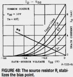
As the operating point is very close to Vgs = 0; small changes in Vp aren't going to really affect much, just slightly change the curve slope. Idss seems much more important (kind of like plate current in tubes). We're not operating the jfets way down at the bottom of the transconductance curve (aka cutoff in tube parlance).
Should I go for 5% match tolerance on Vp instead?
-Kent
Last edited:
- Home
- Source & Line
- Analogue Source
- Simplistic NJFET RIAA