Hi folks,
I've been slowly working on a 6 channel mic preamp and powersupply. The PSu discussion is here: http://www.diyaudio.com/forums/power-supplies/189012-mic-pre-phantom-power-psu-questions.html
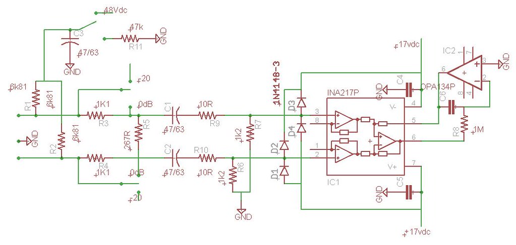
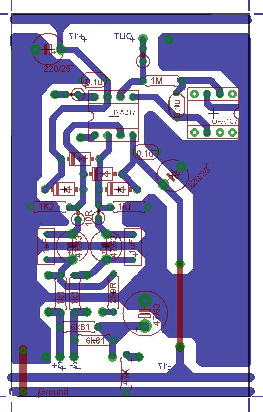
The preamp, at least the first two, are INA217 based. I have included a basic schematic and PCB layout below. The schematic borrows form the INA217 and the THAT1510/12 datasheets. I pulled the constant impedance -20dB pad from the THAT notes.
I'm ready to etch and populate a board (after I give the PCB a final check and cleanup) but wanted to ask for a critique on both before I proceed. I'm a neophyte when it comes to electronics and especially audio, though I have made some projects of similar level already. Many of the rules and best methods of design and layout are new to me though, hence my post here today.
Background: This will be used as a preamp stage for a Tascam US800 interface. The phantom on that unit is very noisy and the built in preamps suck, but it can record 8 channels simultaneously so that fits my needs. I made a prototype differential and buffered preamp using OPA2132 and it worked great with the Tascam. I'll be recording mostly acoustic strings (guitar, upright bass, violin, etc), voice and possibly drums. My current mics include a few each of Shure sm57 and sm58 and a cheapo Berhinger C1 condenser. We'll eventually upgrade to some better condenser mics so I'm trying to make this reasonably "future-proof".
I'd appreciate people's opinions on both the schematic and layout. Basically, I'd like to make sure that I am implementing the -20dB pad correctly and if there are major issues in the design of my board (not proof-reading so much as, "don't put X by Y, it will feedback", etc).
I'd also like to here thoughts on incorporating a balanced driver. I have several free sample DRV134 on hand but I don't know how important it is for me. I can't imaging having a patch cable longer than a couple feet so I suspect unbalanced from preamp to interface would be fine. If it greatly improves sound or decreases noise, I'd incorporate it into the design.
As for the board, I have designed it to be copy and pasted in photoshop for as many chained together as I want (6 perhaps for me). That is why I have run the ground and dual supply along the top and bottom edge of the board, to save having 6 supply wire sets. I have omitted the gain resistors between pin 1 and 8 on the schematic. The is provisions for an ~10R resistor on the board by pin 8 and solder pads for a 10K reverse log pot that I will add a 2k2 resistor from one lug to wiper to improve the distribution swing. I may also use either a switched pot, or a spst switch to break the connection to completely silence the channel (gain 0dB).
Phantom will go from the PSU to individual SPDT switches on the face plate for each channel.
Looking forward to reading your thoughts.
Dennis
I've been slowly working on a 6 channel mic preamp and powersupply. The PSu discussion is here: http://www.diyaudio.com/forums/power-supplies/189012-mic-pre-phantom-power-psu-questions.html
The preamp, at least the first two, are INA217 based. I have included a basic schematic and PCB layout below. The schematic borrows form the INA217 and the THAT1510/12 datasheets. I pulled the constant impedance -20dB pad from the THAT notes.
I'm ready to etch and populate a board (after I give the PCB a final check and cleanup) but wanted to ask for a critique on both before I proceed. I'm a neophyte when it comes to electronics and especially audio, though I have made some projects of similar level already. Many of the rules and best methods of design and layout are new to me though, hence my post here today.
Background: This will be used as a preamp stage for a Tascam US800 interface. The phantom on that unit is very noisy and the built in preamps suck, but it can record 8 channels simultaneously so that fits my needs. I made a prototype differential and buffered preamp using OPA2132 and it worked great with the Tascam. I'll be recording mostly acoustic strings (guitar, upright bass, violin, etc), voice and possibly drums. My current mics include a few each of Shure sm57 and sm58 and a cheapo Berhinger C1 condenser. We'll eventually upgrade to some better condenser mics so I'm trying to make this reasonably "future-proof".
I'd appreciate people's opinions on both the schematic and layout. Basically, I'd like to make sure that I am implementing the -20dB pad correctly and if there are major issues in the design of my board (not proof-reading so much as, "don't put X by Y, it will feedback", etc).
I'd also like to here thoughts on incorporating a balanced driver. I have several free sample DRV134 on hand but I don't know how important it is for me. I can't imaging having a patch cable longer than a couple feet so I suspect unbalanced from preamp to interface would be fine. If it greatly improves sound or decreases noise, I'd incorporate it into the design.
As for the board, I have designed it to be copy and pasted in photoshop for as many chained together as I want (6 perhaps for me). That is why I have run the ground and dual supply along the top and bottom edge of the board, to save having 6 supply wire sets. I have omitted the gain resistors between pin 1 and 8 on the schematic. The is provisions for an ~10R resistor on the board by pin 8 and solder pads for a 10K reverse log pot that I will add a 2k2 resistor from one lug to wiper to improve the distribution swing. I may also use either a switched pot, or a spst switch to break the connection to completely silence the channel (gain 0dB).
Phantom will go from the PSU to individual SPDT switches on the face plate for each channel.
Looking forward to reading your thoughts.
Dennis
Last edited:
I would be very interested to hear people's thoughts in how to ground this. Someone suggested to me before that star grounding would be important with multi channel setup. Does that apply to just the signal grounds or what. For example, should I have the input and output signal to a common star ground as well as one wire connected from the ground pour also? Should there be separate grounds for each channel or should all be connected at a single star point?
Thanks everyone!
Thanks everyone!
Mostly pretty good but you omitted the gain control resistor from your schematic. While there is no indication on the schematic I see a pair of pads on the PCB. Are you intending to remote the gain pot? Being on the '-' inputs of the amps capacitance is an issue.
I built a mic preamp long ago very similar to Elliot Sound Product project 66. I set the gain to 46 dB and nearly never touch it from recording mass choral to the tick-tock of the mantle clock. Mine doesn't have the 20 dB pad. The only time I ever had an overload problem was recording a brass ensemble in a small room. I didn't have a scope to verify what was going on but I believe the AKG C-452 internal preamp was the culprit and I don't have the pad modules to place under the capsules. I changed to a pair of AKG D-200 dynamics so solve that. Brass is LOUD !!!
You have a good preamp with lots of headroom and the input pad for those rare occasions. I recommend putting a gain pot directly on the board and if it bothers you not being able to 'diddle', drill a hole in the box so you can get at it with a 'tweaker'. I predict once you get it dialed in you won't adjust it much at all.
I prefer having a known calibrated preamp so if there are any differences between channels I can swap mic cables and be certain it's NOT the preamp causing an imbalance.
I'm not sure how much you'll need the servo - if at all. Integrators by their very nature constantly wobble back an forth. If you had no input and digitize the output and analyze the data you'd find a cyclic pattern.
You might want to get a couple OPA137 that they recommend for the servo. The open loop gain is lower as is the bandwidth. You don't need those parameters in a servo loop.
I completely forgot. Is that a double sided PCB with those red traces? If it is you can do a much better job with the grounding by having a plane. If it's single sided then never mind.
G²
Last edited:
G^2,
Thanks so much for your reply. I did omit the gain resistors onto schematic to save time. Guess I forgot to clarify that in my original post. I am planning to remotely mount a gain pot on the face plate. While this is a preamp, it is intended to completely replace my inertace amp and controls so adjustability of the INA217 gain seems important to me. The pans for the pot are by pin 1 and 8 of the ina217. There is a series ~10R at pin 8 to set max gain at ~60dB.
I may not need the pad but I wanted it in case, as I may try close micing a drummer friend who is a pretty hard hitter. The -20db pad switch pads on the pcb are next to the 1k1 series resistors.
You said "being on the "-" inputs of the amps capacitance is an issue, I'm afraid I don't know what that means. Would you mind explaining?
I'm afraid i don't follow if you suggest I need the Opa137 dc servo or not? I have included it though.
The PCB is not double sided, I just used that to indicate jumpers. Sorry to confuse.
Do you think there would be an issue copying this 5 more times and printing all on one board? By that I refer to how i have run the ground and supply traces.
Thanks so much again. I just breadboarded this (omitting the phantom) and it sounds good even surrounded by spagetti and florescent lights🙂.
Should I have an DC from pin 6 to ground?
I seem to get about 300mv-420mV depending on the gain.
With or without the servo? I'd expect close to 0 without a servo and nearly 0 with. Close to 0 = <100 mV. Nearly 0 = < 5 mV. Change of offset vs gain indicates an imbalance on the inputs. The voltage may be lower than your meter can measure but the extra 10 meg on the pins one at a time might change the output. It's possible the leakage current could come from the input capacitors or your protection diodes (or contaminants on the package(s)). First to do is short pins 2 and 3 to ground and measure the output offset.
The 20db pad doesn't look right at all to me. Can you post a link to the THAT paper?
I just opened up my 1982 non-servo mic preamp. -54mV left, -144 mV right. I don't consider this an issue and have no plans to 'fix' it. I.E it ain't broke.
G²
Thanks for the reply G^2.
With servo, at 60dB gain I get ~400mv, 0dB gain ~300mV.
No servo and pin 5 of the ina217 grounded, 70mV @ 60dB gain, 4mV @ 0dB gain.
I've checked this twice. I've also tried a different ina217 and a different opa137. Absolutely no real difference.
Note, this does not change if there is either no mic connected, or a cheap fender dynamic connected.
If I short both input sides to ground, 0dB gain goes down to about 180mV, full gain goes over 2volts. Voltages are always negative, btw, with my meter ground probe to the ground.
However, there seems to be some fluctuation in the offset simply by jiggling and moving this, though it always seem to restabilize at the voltages I have already listed.
I am not using the protection diodes on the breadboard because I am not connecting phantom power. I left the 6k81 resistors from inputs to ground through a series 47K resistor, as the ina217 datasheet shows for phantom

The pad is straight from the That Design Note 140, http://www.thatcorp.com/datashts/dn140.pdf Sorry I can't find an image to link directly.
There are pads next to each 1k1 lead in series with the input. I would use a SPDT switch. One way and the left side is "open", path is through the 1k1 resistors. Additionally, on the right side th path is through the 1k1 and the switch closes the connection between the 267R and the input. The design notes describes this as keeping the impedance the mic sees always at ~2kohms, and does not affect the phantom being on or off.
At what DC offset do I need to add an output series cap and a R to ground?
Thanks, Dennis
With servo, at 60dB gain I get ~400mv, 0dB gain ~300mV.
No servo and pin 5 of the ina217 grounded, 70mV @ 60dB gain, 4mV @ 0dB gain.
I've checked this twice. I've also tried a different ina217 and a different opa137. Absolutely no real difference.
Note, this does not change if there is either no mic connected, or a cheap fender dynamic connected.
If I short both input sides to ground, 0dB gain goes down to about 180mV, full gain goes over 2volts. Voltages are always negative, btw, with my meter ground probe to the ground.
However, there seems to be some fluctuation in the offset simply by jiggling and moving this, though it always seem to restabilize at the voltages I have already listed.
I am not using the protection diodes on the breadboard because I am not connecting phantom power. I left the 6k81 resistors from inputs to ground through a series 47K resistor, as the ina217 datasheet shows for phantom
The pad is straight from the That Design Note 140, http://www.thatcorp.com/datashts/dn140.pdf Sorry I can't find an image to link directly.
There are pads next to each 1k1 lead in series with the input. I would use a SPDT switch. One way and the left side is "open", path is through the 1k1 resistors. Additionally, on the right side th path is through the 1k1 and the switch closes the connection between the 267R and the input. The design notes describes this as keeping the impedance the mic sees always at ~2kohms, and does not affect the phantom being on or off.
At what DC offset do I need to add an output series cap and a R to ground?
Thanks, Dennis
I just completely tore down the breadboard and re-did it in a different part of the board.
No difference at all what so ever. Hope springs eternal but no luck.
Thanks, Dennis
No difference at all what so ever. Hope springs eternal but no luck.
Thanks, Dennis
Have you stuck a scope on the output? Make sure you're not oscillating. If the output is clean and AC free, then check the DC voltages between pin 2 and ground and pin 3 and ground.
Thanks Sy.
Unfortunately I do not have a scope🙁
DC voltage between pin 2 and 3 to ground is 4 and 5mV respectively with no mic connected.
Does it look like there is anything wrong with the schematic that should cause this?
My meter only goes to 0.1Vac but I get no vac on the output of the amp.
Testing the ac on the PSU output shows 0 on negative rail and ~40 on the positive, but isn't that a result of the meter not knowing how to handle the DC on an AC setting?
What sort of mV on the output would require a blocking cap on the output?
My issue really seems to be coming from the DC servo using an opa134.
I remove the servo and get about 70mV with no source attached. If I attach a mic offset drops down to almost zero. If I add a electrolytic cap in series with the output, DC ranges from ~40mv with no mic connected to ~4mv with a mic connected.
I remove the servo and get about 70mV with no source attached. If I attach a mic offset drops down to almost zero. If I add a electrolytic cap in series with the output, DC ranges from ~40mv with no mic connected to ~4mv with a mic connected.
With the servo chip in place, what voltage do you see on its (OPA134) output? Is the differential voltage at the inputs of the servo zero?
Thanks Sy.
The output of the OPA137 (pin 6) with the servo hooked up is negative 270-370mV, dependent on gain of INA217. The meter ground probe is on the ground point of the layout. The output of the INA217 (pin 6) is the same voltage with the servo connected.
If I disconnect the servo completely and ground pin 5 of the INA217, DC voltage is -4 to 47mV depending on gain.
All these measurements are with no mic connected and the mic outputs (the amp inputs) not grounded.
Circuit is: Mic output (xlr pin 2 and 3) -> 47uF/63V electrolytic 10R metal film -> to pin 2 and 3 of the INA217. Inputs grounded after the 10R with 1k% metal film. 17.5vdc positive and negative rails bypassed at the pins with 0.1uF ceramic. The servo is set up exactly as shown on the INA217 datasheet. INA217 pin 5 (Ref) to out of 137 (pin 6). INA217 out (pin 6) to in- (pin 2) of opa137 through 1M series resistor. ina215 pin 5 and 6 series through 0.1uF Wima polyester. OPA137 pin 3 (in+) to ground.
I just completely tore down the breadboard and re-did it in a different part of the board.
No difference at all what so ever. Hope springs eternal but no luck.
Thanks, Dennis
Sy is right, time to get a scope on it. Unfortunately I see in a later post you don't have one. The 0.1 VAC on the meter may be problem if the circuit is oscillating it my be higher than the meter can read. My Fluke 8060 is flat to 100 KHz but if it was oscillating at a MHZ the meter would be nearly useless while even a really bad scope gets to several MHz. My old Tek is good to 250 MHz.
The pad in the THAT paper is correct but you didn't copy it correctly.
That amp has a lot of gain and will be difficult to tame on a breadboard mainly because of poor grounds. That should clear up on a good PCB.
G²
Thanks G^2!
I was beginning to think I need to just etch one channel and see. Thus circuit has been used many times by others without this issue.
I'll look into the pad more closely but where is mine wrong? It seems like no pad shorts the series 1k1 resistors and bypasses the 267R divider resistor between inputs. Pad removes the short and connects the 267R between inputs. I'll double check my layout for sure!
Thanks!!
The DC servo is not powered correct?
I hope it's powered, otherwise it won't work!
I wondered about that. Initially I drew my schematic and the board with the opa dc servo powered. Then I noticed that neither the BB datasheet for the ina217 nor any of the ina217 board layouts I saw posted by others had the dc servo powered.
I thought of this last night but did not feel like getting out if bed to try it🙂
So I guess everyone who posted their layouts online never bothered to check the DC offset afterwards?
Anyway, I'll try that when I get home tonight.
Thanks!
Dennis.
I thought of this last night but did not feel like getting out if bed to try it🙂
So I guess everyone who posted their layouts online never bothered to check the DC offset afterwards?
Anyway, I'll try that when I get home tonight.
Thanks!
Dennis.
- Status
- Not open for further replies.
- Home
- Live Sound
- Instruments and Amps
- INA217 mic preamp critique and questions