I wondered about that. Initially I drew my schematic and the board with the opa dc servo powered. Then I noticed that neither the BB datasheet for the ina217 nor any of the ina217 board layouts I saw posted by others had the dc servo powered.
I thought of this last night but did not feel like getting out if bed to try it
So I guess everyone who posted their layouts online never bothered to check the DC offset afterwards?
Anyway, I'll try that when I get home tonight.
Thanks!
Dennis.
When I would draw schematics for any board I always connect the power pins to the correct net and then hide the pin. It is understood that all opamps and semiconductors need power to operate. Seeing the pin marked as power is just extra stuff on the drawing that doesn't aid in understanding the functions so we leave it out.
With that in mind you now know why I asked about using the net list. It may seem cumbersome at first but it makes life so much better in the long run.
If I ever post any circuits you can be certain I have built it and it will do what I say it will. BTW I check output offsetts and everything else just because it's a great way to double check yourself.
G²
Ah ha! Now I feel like a dunder-head.
Thanks for the help everyone!
G^2 and everyone else who has helped, I hope I did not make any of you think I was referring to you when I said people did not check offsets or posted something not right.
I have found two specific INA217 pcb board layouts in the internet that use the OPAxxx DC servo. Neither of them have power applied to the DC servo. I think the confusing thing for neophytes like myself is that if the datasheet left off the power to both ICs we woudl assume both had it. But, the INA217 datasheet specifically shows power to the chip on the schematic but not for the OPA137. Its perfectly understandable now, but I guess I understand how I and two others have made this same mistake.
Anyway, DC offset now is 0-3mV. As I change the gain pot I can watch DC jump up t ~15mV and go back to zero within 1/2 second or something. I am not considering this an issue.
Thanks for the help!
What is the best way to deal with input, output, and power grounds? Should all three have go to a star ground or should the input or output float, or be only together? I known it sounds like a simple question but in reading I've see mention of floating the output ground and other references to treating source and power grounds separately.
So, I thought I'd ask now. Thanks!
An Sy, me too!!! Thanks especially to you and G^2 for taking the time to help menso much. Honestly, I learned a great deal here, much more than if everything ha been right from the start and I had not been such a bonehead")
Thank you!
So, I thought I'd ask now. Thanks!
An Sy, me too!!! Thanks especially to you and G^2 for taking the time to help menso much. Honestly, I learned a great deal here, much more than if everything ha been right from the start and I had not been such a bonehead
Thank you!
Is it right to say that I should connect the PSU ground to a star ground near the PSU. I then isolate the ground of each amp circuit (say I have 6 of these in a case) from the other circuits and run each of then individually to that star ground. Pin 1 of the balanced XLR inputs should connect right to the chassis not to the board. The shield of each 1/4" output should go individually to the star ground not to the board. If necessary I can tie each of the input and output shields to chassis with a small capacitor to shunt RFI away from the circuit.
Is the crappy paint picture generally right? I've not drawn in a fuse, switch, etc.
I generally see in images on the net things grounded/wired like this link:Kev's Dual Mic-Pre
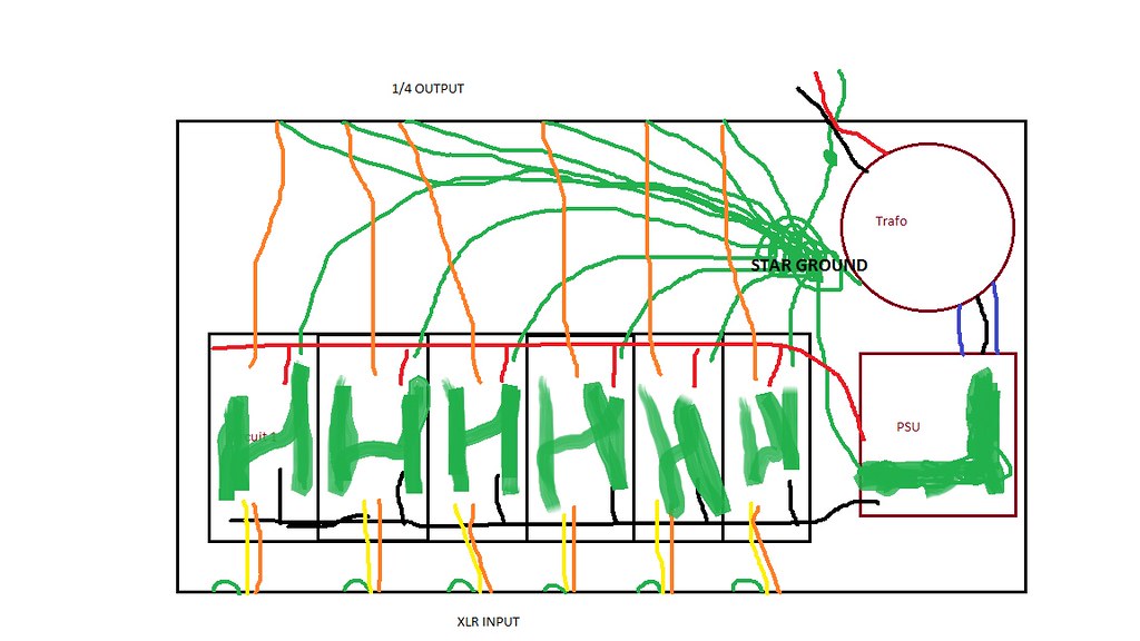
grounding by Dennis Dietz, on Flickr
Thanks!
Is the crappy paint picture generally right? I've not drawn in a fuse, switch, etc.
I generally see in images on the net things grounded/wired like this link:Kev's Dual Mic-Pre
grounding by Dennis Dietz, on Flickr
Thanks!
<snip>
Anyway, DC offset now is 0-3mV. As I change the gain pot I can watch DC jump up t ~15mV and go back to zero within 1/2 second or something. I am not considering this an issue.
Thanks for the help!
But the important questions are. How does it sound? Is it as quiet as you hoped? I've only run AKG and Sony mics through the preamp. In all cases the ambient noise in the room - even empty - was significantly greater than the preamp noise. And listening through headphones I can always hear way more than my unaided ears alone. I really like AKG condenser mics.
When measuring THD way back when it was new the 30 Hz THD was 0.02%. I was intending to record pipe organs with 32 foot pipes (16 Hz) and I didn't want the low end clouded from crappy transformers. It never occurred to me to get better transformers. just get rid of them altogether.
G²
G^2, I'll find out soon how it sounds. My breadboard circuit did not seem to have imediately noticeable sound with only a quick listen last night. My wife is the real musician so next chance we get I'll record her and see. Thanks for the condenser mic recommendation. We need a better one. Do you have specific models you like for certain applications, or ones you dislike?
Tico, I do intend to try some other chips, especially the one you mention and the THAT chips.
Tico, I do intend to try some other chips, especially the one you mention and the THAT chips.
G^2, I'll find out soon how it sounds. My breadboard circuit did not seem to have imediately noticeable sound with only a quick listen last night. My wife is the real musician so next chance we get I'll record her and see. Thanks for the condenser mic recommendation. We need a better one. Do you have specific models you like for certain applications, or ones you dislike?
Tico, I do intend to try some other chips, especially the one you mention and the THAT chips.
The Analog Devices SSM2019 is the same pinout as the INA217 and the THAT chips but unless you're unhappy with the performance you can skip it.
As for mics, I've used Sony C-38 dual element large format (30 mm) condensers. I was neither impressed nor depressed about them. I used a pair of AKG C-414s large format dual element that I really liked but those are pretty pricey. I own a pair of AKG C-451EBs with CK22 cardioid capsules. The 451s are small format (15 mm single element) I particularly like the sound of these. The transients on acoustic guitars and bells and triangles are wonderful to me. I've used Sony electret condensers which I didn't like at all. I had some AKG dynamics that were pretty neutral. I worked with Shure SM-58s at the TV station and those were good too. This is just an advanced hobby for me. Broadcast TV pays the bills.
A word of warning on the preamp if you ever connect to a computer sound card or worse yet, the onboard sound system. Your preamp can put out a LOT of Voltage - enough to destroy the sound card. If you intend to use it with a computer you should add some peak limiting diodes on the signal output similar to your protection diodes on the input to the chip. 3 diodes in series in each direction pos and neg to ground will clip AFTER the input overloads but before damage is done. It won't cause sonic damage while preventing electrical damage.
G²
I have two free samples of SSM2019 on the way. Figured they are swappable and free so why not
G^2, thanks for the mic advice, I'll definately remember that.
Also tha is for the warning on voltage with sound cards. Do you think there would be a problem using this on a USB interface, specifically the Tascam 800?
G^2, thanks for the mic advice, I'll definately remember that.
Also tha is for the warning on voltage with sound cards. Do you think there would be a problem using this on a USB interface, specifically the Tascam 800?
The datasheet for my interface lists maximum inputs as:
Mic balanced:+2dBu
Line balanced:+20 dBU
Instrument unbalanced:+3dBV. Volts
Now I'm sure I can send a hot signal through the preamp and measure it's vac with my multimeter. Not sure how accurate that will be but doable. I don't know what to expect from a hot mic on the input so I don't know how much to expect voltage wise in the output.
I also can't currently fathom what happens if I plug a unbalanced out from the preamp into the balanced input of the interface. The product sheet lists the above max levels but each input type overlaps other (all have combo xlr/trs, but lists 1-6 as mic in, 3-6 as balanced line in, 1-2 as unbalanced instrument). There are no selector switches, inst switches or pads on the device.
Thought are appreciated!
Last edited:
With the preamp set for my typical 46 dB gain, I have seen the output clip at 25 V p-p with loud transients. Since the input on the PC runs a single 5 Volt supply, anything greater than 5.6 will start shunting through the protection diodes in the PC. If that current gets high enough it could take out the audio chip. Same story for USB. The nice thing about USB is that if you DO trash it it's easily replaced. Not so with codecs on the motherboard.
Looks like the Tascam (?) is pretty tolerant of loud inputs. Hope it works well for you.
G²
Looks like the Tascam (?) is pretty tolerant of loud inputs. Hope it works well for you.
G²
I have two free samples of SSM2019 on the way. Figured they are swappable and free so why not
From what I understand, they are identical to THAT1512.
According to this online calculator (dB dBu dBFS dBV to volts conversion - calculator volt volts to dBu and dBV dB mW - convert dB volt relatioship relation convertor converter calculation online attenuation loss gain ratio reference audio engineering sound recording dBFS dBVU 0 dB audi), the balanced line inputs have about 22V p-p. The unbalanced instrument inputs only have 4V p-p.
I'm not sure what happens if I plug an unbalanced cable into the balanced line inputs of the interface.
Seems like I need the output protection diodes, right?
My outputs on the preamp are unbalanced though. Should I add a circuit to balance them? With unbalanced, the protection diodes would go from the single output to ground or to the power rails?
The ina217 datasheet uses diodes from the power rails to the input signals. The THAT sheet uses diodes from input to ground and from the power supply rails. I don't quite ge yet how all that works. I believe the diodes shunt vintages above their break point to the power rails, but why power rails and not just ground. Power rails keep the diodes closed unless the reverse voltage is to high otherwise the diodes would not fxn right???
Hmmm, this all just got a lot more confusing to me
I was able to test the breadboarded circuit last night. I found vdc on the output as high as 9.8V using my cheap multimeter on it's lowest setting of 200V. The voltage was with as hard and intense of blown air I could muster. Close hand claps and load singing where much lower, 2-4V. I've not had the chance to try a hard played guitar or drums.
10Vac is 22dBU and 28 p-p according to the calculator I linked above. 28p-p seems close to G^2 statement a couple posts up and is 2dBu above the maximum input listing of my interface.
Do I need protection diodes on the output? Does that mean I should use a Zener with a reverse breakdown of 8 volts (20dBu)?
I also noticed DC on the output would go up as high as 0.4v very briefly (less than a second) with the inputs described above. I using the dc serve which shows 0-1vdc with no signal. Dc seemed to stay <100mV or even 50mV unless the input was very high.
Thoughts on output protection diodes and if the DC above is a concern.
Thanks! dennis
I'd be more inclined to put protection Zener diodes at the input of the interface. That's the thing you're trying to protect- it may be used with other preamps or you might want to use this preamp with another interface. No functional difference, just more a matter of convenience and versatility.
It's possible your interface already has input protection- you might check the schematics or ask the manufacturer.
The mike levels you're getting are pretty typical. Be careful about blowing into the mike, though- that's a common way to damage diaphragms, and it will absolutely destroy most ribbons.
I'll check to see if the interface has protection. If I need to add something though, I personally would prefer to add it to the new preamp ad I can incorporate it onto the birds before etching.
May I ask for a diode recommendation? G2 mentioned 3 in series. Is that 1N4148? What do 3 in series do? And to check, that us from the output if the ina217 to each power rail, identical to the input except series, or from output to ground?
Thanks for the reply!
As for mics, thanks for the warning. Luckily, I was not concerned with the $5 used radioshack dynamic I was testing with.
May I ask for a diode recommendation? G2 mentioned 3 in series. Is that 1N4148? What do 3 in series do? And to check, that us from the output if the ina217 to each power rail, identical to the input except series, or from output to ground?
Thanks for the reply!
As for mics, thanks for the warning. Luckily, I was not concerned with the $5 used radioshack dynamic I was testing with
.- Status
- This old topic is closed. If you want to reopen this topic, contact a moderator using the "Report Post" button.
- Home
- Live Sound
- Instruments and Amps
- INA217 mic preamp critique and questions