Problems of my DCB1 finally come:
Everything seems okay except the output port: L, R and Gnd are all shorted;
speakers only get loud hum....scary so I turned it off.
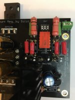
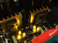
4 Matched sk170s are from Spencer-perfectly matched at 8.0mA.
R1 = 3.3Ω/30W for 600mA hot rodding.
all V measurements are good.
For the orange relay, I remember it is 12V so I shorted the resistor.
Appreciate the help") (It is bed time here so I check in the morning)
(It is bed time here so I check in the morning)
Everything seems okay except the output port: L, R and Gnd are all shorted;
speakers only get loud hum....scary so I turned it off.
4 Matched sk170s are from Spencer-perfectly matched at 8.0mA.
R1 = 3.3Ω/30W for 600mA hot rodding.
all V measurements are good.
For the orange relay, I remember it is 12V so I shorted the resistor.
Appreciate the help
(It is bed time here so I check in the morning)Attachments
Hi Salas,
Here is my measurements this morning.
yes there is a click from the relay after 6 seconds.
I measured the continuity of the output holes after the relay click:
R and GND are shorted(beeping) (offset=233mV!!!)
L and R are shorted (beeping)
L and GND are NOT shorted (no beeping)
When power off, all three holes of output are shorted.
I finished the built yesterday and that was my first test with my active speakers.
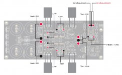
Don't involve the continuity beeper when the circuit is alive. When its powered down, or before clicking, the relay shorts outputs to ground anyway in all modern DCB1 PCB versions. Only measure DC offset. Clean flux residue thoroughly on both sides. Especially in the four signal JFETS and output relay area.
The noted voltages are alright (except the one side offset in red). The voltage drops on the setting resistors suggest circa 460mA for 3.3R you used. For more you would need green LED triplets but in my opinion that's enough hot-rod you already have.
The noted voltages are alright (except the one side offset in red). The voltage drops on the setting resistors suggest circa 460mA for 3.3R you used. For more you would need green LED triplets but in my opinion that's enough hot-rod you already have.
Thanks Salas. I have gone crazy with 3.3Ω for 600mA Hot rodding! It should be good.
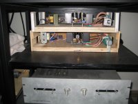
What ! only 3.3 ohm
Look mine at 1.2 ohm (top one) for 3 years 24h/7d (never stop it) 60 C
And you see (under) CAT(Convergent Audio Technology) collecting dust !
Don't ask me why
Attachments
What ! only 3.3 ohm
Look mine at 1.2 ohm (top one) for 3 years 24h/7d (never stop it) 60 C
And you see (under) CAT(Convergent Audio Technology) collecting dust !
Don't ask me why

BTW about noises when with very sensitive speakers, is there any wire for referencing the chassis to the PCB zero? Either straight to it or through a 10-100 Ohm resistor? If not, test that, it may help. If helpful indeed, remove the simple test wire, solder together two 5A diodes in parallel but with their stripes at opposite ends, parallel a 10 Ohm 3W and a 0.1uF film cap to those. Bolt one end of that safe ground lifting/zero reference system to chassis and wire its other end to a PCB zero. There is a convenient zero middle pad marked G in the regulators output vicinity between V+ & V- pads.
Hi Salas. I am finally going back into my DCB1 to try and sort some of the issues we talked about a while ago. I wanted to ask a few questions about the advice you gave above concerning grounding. I am trying to use what I have on hand to implement this safety ground arrangement.
Is it possible to use a pair of MUR860 back to back for the parallel reversed polarity diodes?
What voltage should the .1uf capacitor be rated at? I have some .1uf 50V RadioShack gumdrops.
I currently have 10 Ohm 3 Watt resistors mounted in the DCB1 to give me about
200ma of current. I was going to pull them to use one for the safety ground and try mounting the 5 Ohm 3.75W that came with the kit to run some more current. Do I have to change any LEDs or anything else to do that?
I’ll also be replacing the mono Noble pots I had a problem with. I mapped them on some graph paper and they turned out to be linear taper. I found some affordable mono Clarostat log conductive plastic pots to try. Going for a Goldpoint or similar doesn’t make sense for me at this point as I already took the leap and ordered a SE Iron Pumpkin from Zen around Xmas.
Beyond that, I haven’t decided if I’m going to completely re-wire the inputs with twisted pairs or just try adding shielding to what’s there already. Working with the mini Greyhill selector switch was a real chore.
The last thing I may try is adding some Jensen trannies at the output if I have time. I’m coming up short when I am using my phono setup and am hoping the extra 6dB or gain might help.
I’ll also be replacing the mono Noble pots I had a problem with. I mapped them on some graph paper and they turned out to be linear taper. I found some affordable mono Clarostat log conductive plastic pots to try. Going for a Goldpoint or similar doesn’t make sense for me at this point as I already took the leap and ordered a SE Iron Pumpkin from Zen around Xmas.
You can make the linear pots work pretty much like a log pot with the addition of a resistor - see here: The Secret Life of Pots
As long as the impedances still work in the circuit... Some preamps use this since dual linear pots typically track better than dual log pots. Since you are trying things out, I just thought this was something quick you could try without getting new pots.
@chromenuts
-Yes you can also use MUR860s back to back
-The voltage rating is not crucial. That cap is to form a low impedance RFI path to chassis. Film capacitors and C0G ceramics are good for that use.
-No changes to LEDS or anything else for parts when upping hot-rod level with lower value current setting resistors. But check that the TO-220 bridge diodes don't go over 85C or sink them. Also, if the Mosfets sinks go over 65C enlarge them.
@bkdog...I’ve already pulled the Noble pots and made the modifications to mount the Claroststs. It was suggested that I could modify the Noble pot with a tapering resistor by the seller I got them from on eBay. I wasn’t sure if it would create more problems than it would solve concerning my phono source I am struggling to get working properly with the system, so I scratched the idea for now. Thanks for the article link though.
@Salas Thanks for the guidance. I will definitely monitor the bridge diodes and heat sinks of the mosfets.
@Salas Thanks for the guidance. I will definitely monitor the bridge diodes and heat sinks of the mosfets.
Hi Salas
I’m sorry, another question came up that I wanted to confirm with you.
I am assembling the safety ground from the diodes/cap/resistor in parallel and anchoring one end of it to the chassis and wiring the other end of it to the 0 pad on the center of my Hypnotize board.
Should I then star ground all my input rings and the pot grounds to the same point that the hypnotize connects to the safety ground so everything grounds through the safety ground?...or should the input rings and pot grounds just go directly to the chassis?
Previously my input grounds were bused together, connected to their corresponding left or right channel’s mono pot ground, the pot grounds were then linked and connected to the input ground on the Hypnotize.
Last edited:
Thanks Salas
I am going to reconnect the signal wiring as I had them but try to shorten the connections as possible so there are no large loops. It has worked fine as it was with several different combinations of equipment and speakers.
I’m trying to make a limited number of changes at one time and then test the Hypnotize to avoid any big screw ups.
I pulled the 10 Ohm current setting resistors and replaced them with the 5 Ohm 3.75 Watt resistors that my hot rod kit came with to increase the current.
Since one of my goals is to add some gain to help my phono stage that appears to be struggling to sing in my current system, I also pulled the 220 Ohm series resistors on the output of the Hypnotize and put jumpers in their place. Zen Mod said this was necessary in order for the buffer to be able to drive the Jensen JT-123-FLPH I want to add at the output.
I added some small heatsinks to the MSR860.
I was concerned about heat dissipation with the new current setting and also wanted to make sure there wasn’t a DC offset issue that I needed to worry about going into the Jensens. I decided to reinstalled the Hypnotize in the chassis so I could power it up and re-test it.
The Hypnotize fired up as usual. Once the relay clicked, I saw about -.8 mV offset on one channel and - 1.8 mV on the other. They stabilized around -1.6 or -1.7 on both channels after a few minutes. The offset is a little lower when the inputs are shorted to ground...about -1.5mV. I power cycled it several times and there doesn’t seem to be any big jumps in offset. I think one time during shut down I saw it jump to 2 mV.
I tested the Vout +/- rails and got around -9.61 V and 9.58 V. They both stabilized closer to +/- 9.58 after 10 to 15 minutes, but the negative rail seems to want to stay .01 V or so higher.
I recently re-read the PDF that was circulated relating to building the DCB1 and this made me think that these measurements didn’t exactly sync with what was expected even though it wasn’t much different than the measurements I posted when I first built my Hypnotize.
The PDF says:
5. HOW TO KNOW IF THE CIRCUIT IS WORKING PROPERLY
In general, if its not noisy, too hot, or having high DC offset, and the +reg is 3% more on average for matched leds on both banks and between them, plus side R5 has more mV than neg side, is good to go.
Salas.
1. See that you have 2V+/-0.3V across R1 combinations. That says the shunts CCS currents are normal.
2. Check that you hear the output relay clicking one time 3-4 seconds after power on.
3. See that you have less than +/-5mV DC offset on the audio outputs.
4. See that you have +Vout a bit more than - Vout.
If all of the above are OK, connect to stereo. Check for ground loops. If the background is silent, play some music.
I am ashamed to say I never successfully measured “2V+/-0.3V across R1 combinations”. I’ve searched endlessly via Google and the forum search to try and find details on how to do this properly, but with no success. I had found a Mesmerize schematic with resistor labeling pointing to a R1 220R resistor that appeared to be in the buffer section, but no measurement across the resistor, to ground or otherwise gave me a voltage reading as described. I eventually gave up based on the fact that the relay had clicked, nothing had exploded, the DC offset was within expectations and the Vout readings seemed reasonable.
At this point I would just like to know that even though things aren’t exactly as described in the PDF, that nothing is amiss or sub-optimal as I try to move forward.
I still haven’t confirmed the voltage measurements surrounding R1 described above, not even sure they matter.
My Vout measurements are almost exactly the same for the +/- rails as opposed to the positive rail being 3% or so higher as expected and they are lower than expected.
Another measurement I never figured out how to take is the amount of current running through the circuit. I have searched and read many posts that seemed to discuss the subject of current setting but never deciphered what the actual process was. Perhaps it was because the builders understood the circuit design and layout. Unfortunately, I don’t understand the circuit or layout. To me these are like electronic lego sets and I rely on instructions more than most I think. Now that I have changed the resistors setting the current I would like to understand how to measure it.
I have measured the temperature of the IRFP mosfets at about 105-107 degrees F and the MSR860 regulators at about 95 degrees F after the Hypnotize has been running at idle with no signal applied to the input for 30 minutes or so.
I was expecting more heat than this and was under the impression that swapping in the 5 Ohm 3.75 Watt resistors would take me closer to 600ma of current? Perhaps that is not the case given that I seem to have lower than normal Vout measurements and no bias toward a higher Vout+?
For reference, I am using an Antek 0515 transformer which is giving me 12.4V from the secondaries at the input of the Hypnotize.
- Home
- Source & Line
- Analog Line Level
- Salas hotrodded blue DCB1 build