This is my first post. What a great site. I hope someone can help me?
Sorry for the lengthy preamble...
I have owned by SA5 since the mid-eighties. It has given me very little grief and most of the few repairs required over these 20+ years were simply replacing (DIY) something that had visually fried, started to bulge, or a bad tube. I am armed ownly with a DVM, a tube tester, and only enough knowledge to get me into trouble and stubborness for DIY before sometimes finally going to a service tech.
Over the last few months I had noticed that my 5651 tube was taking longer and longer to turn on. Finally it was such that it did not turn on at all, yet after power down and up it would then turn on. I checked all the tubes and found that the 6JC6A tube had shorted. Upon replacing the tube, things seemed to work for awhile, but symptoms started again shortly after.
While the unit was on and the cover off, I noticed I had not seated 6JC6A tube straight, so gave it a wiggle. Well, what I found out, putting pressure on the tube, the 5651 next to it came gratefully on... but then off again.
So drastic measures, out came the preamp into my torture chamber (my rec room carpeted floor). Covers off, better lighting, and through wiggling and tapping I discovered 4 cold solder joints between the main and the perpendicular board, a crumbling tube socket (6GC5) and heavily discolored board area around same socket, in fact a little like carmel.
Joy oh Joy, something I can fix. Ordered parts/tubes, resolderd joints, replaced tube socket, scrubbed board area clean. Put it all together, it worked fantastic... for a couple weeks...
Again, 5651 not lighting up, 6JC6A shorted, (luckily I bought more than one), will still play, in fact the 6JC6A appears uncharacteristically bright, but certainly I am not leaving it on.
I have a feeling all I did was clean up the symptom, but not the cause.
All I have done further is checked everything over visually, put the DVM on every resistor I could see for anything obvious, but it looks like I won't be getting any accurate readings unless I start pulling resistors out? I have no way of testing the capacitors, or maybe I just don't know how?
Oh, and I did check for continuity the tracings from the main board, across the new solder joints I made, to the perpendicular board, and they seem fine.
I'd really like to get it up and running myself, and I do have a good service tech should I screw things up.
If anyone has any ideas, they would be much appreciated. Sadly, if it is such that it could be one of many things, I may concede and release this creature from my torture chamber and give to my tech.
Many thanks in advance for any help!
Hi leviathon,
Those connections between the main PCB and right angled tube PCB are always a problem. If you have recently gone over them, that's one problem gone.
If memory serves, there were some bad connections in the power supply that would interrupt the heater current to the power supply tubes. This is one of those times when seeing the unit would really help. Early documentation was both poor and a bit scarce, so I go on what they look like for the older ones.
There is a constant current diode as well I think. They break down over 100 VDC, and there should be a 91 volt zener across it. Check for shorts there, and also make sure the operating voltage is around 45 volts across that diode. If the zener conducts, the current will be uncontrolled.
The last thing would be to check the tube sockets of the regulator circuit, and you have found a problem. Make sure the PCB under the socket isn't arcing or tracking. Lights off and have a good look for light where there shouldn't be.
The one place where Counterpoint is very poorly engineered are the power supplies. Almost every one has design or manufacturing issues. The more expensive and complicated the unit is, the less chance there is of fixing it once and for all. In fact, each one I look at in detail becomes a journey now. Under warranty we just fixed them. Now I get involved in redesigning these simply to keep them running. I haven't had to do that with this model - yet.
For the last hint, try using Electroharmonix tubes for the signal path. Any good quality tube will work well for the tubes in the power supply. Try to stay with name brands such as RCA, GE, Westinghouse ... you get the idea.
Good luck, let me know how this works out for you.
Hi SY! Thank you.
-Chris
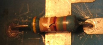
Culprit Resistor?
Well this fellow looks and reads nasty on my DVM. Unfortunately can't quite make out all the band colors? Yellow White White Red with Tolerance Brown? Or Yellow Brown White Red with Tolerance Brown? Or...??? Help!
Thanks in Advance!
Ed
Well this fellow looks and reads nasty on my DVM. Unfortunately can't quite make out all the band colors? Yellow White White Red with Tolerance Brown? Or Yellow Brown White Red with Tolerance Brown? Or...??? Help!
Thanks in Advance!
Ed
Attachments
Things are looking up!
My best guess for the resistor was 49.9k 1%.
As a quick fix I put together 2 x 22k 5% (44K total). The 5651 tube didn't come on before the warm up LED completed it's cycle, but it did eventually come on (within a minute after). It wouldn't come on at all before.
The other things such as the zenor diode checked out okay. And no leakage between pcb traces detected in the dark. (Checking things in the dark were eerie and cool at the same time!)
Will keep my eye on things.
Thank you for input!
Cheers,
Ed
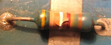
Well this fellow looks and reads nasty on my DVM. Unfortunately can't quite make out all the band colors? Yellow White White Red with Tolerance Brown? Or Yellow Brown White Red with Tolerance Brown? Or...??? Help!
Thanks in Advance!
Ed
Can you zoom out a bit I can see where that resistor is?
Hi leviathon,
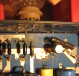
They didn't give us any PCB layout diagrams for these units. So, the best I can do for you is to attach a picture of one I had repaired. I have cropped the photo down to the area you are working in.
When working with high voltage on circuit boards, clean is what you need. That's one reason I keep my work clean. The other reason is that I can see if anyone else has been in there.
Can you do me a favor and trace the resistor to where it connects there? One end will go to one or more components and the other end will do something similar. For example: one end goes to pin 5 on V5, pin 1 on V6, positive end of C52 and the bypass capacitor across it and the other end connects to pin 1 of V7 and many other parts, like 3 499 ohm resistors, the positive end of C56, and more. This would be the cathode of the pass tube, in other words, the output of the regulator. There are some decoupling resistors (499 ohms) between the gain stages and the regulated output. I can try to figure it out exactly from there.
As for the voltage reference tube, it will only light up (strike) once the DC output from the regulator has exceeded the breakdown voltage. So there is a delay there. Due to the high amount of capacitance across that tube (bad design example), and it's series resistor (182 K), there is an additional time delay before it strikes and glows. You should see between 82 and 92 volts across the voltage reference tube if it's operating okay. The regulated output voltage should be around 260 VDC. That will "bite" you if you contact any part of that circuit.
If you look at the component that appears to be a small can in parallel with a larger axial leaded diode, you should be able to measure a voltage drop around 45 VDC. It must be below 90 VDC by a comfortable margin, and above 10 VDC. The metal can device is a constant current diode (breakdown around 100 VDC), and the diode beneath it is a 91 VDC zener diode (1N5378). This measured voltage will rise and fall with the AC mains level, so you need to get a sense of what the average is. You can change this voltage by replacing the resistor in series with it. The nominal value will be 75 K ohm, but it may likely be a different value also. Increasing the value of that resistor (Say ... 82 K ohms) will lower the voltage across the current diode. You can figure out the drop easily enough. The CCS diode should be close to 1.6 mA. Ohm's law, figure out the drops in that circuit.
So, trace away please and I'll try to get you some answers. The continuity function on some meters make tracing easier.
-Chris
Attachments
The burnt resistor is R57. It is 49k9 so you were quite correct.Hope this pic works! Thanks for your help.
R57 and R58 (23k7) form the resistive divider that feeds back a portion of the output voltage of the regulator to the 'error amp' whihc is V6 (the 6JC6A).
The output voltage should be ~ 260V, so R57 has ~ 2/3 of 260 or 173V across it. It dissipates 0.6W steady state. The original part is a Roederstein MK3 rated at 0.6W so it was always going to fail ...
You want to replace this with a much higher power rated resistor. Personally I would be looking for a 5W part. And replace R58 before that dies too.
R58 is, I think, down the other end of that row of parts. I can just read the designators on my documentation. But only just, so go looking for a 23k7 MK3 resistor - it is the only resisotr of that value in that area.
Hi Alan,
I think that 5 watt resistors are too large here. I'd really suggest something more in keeping with the space allotted on the PCB for these parts. As a major service center in Canada (near Toronto where tons of these were sold), we never did see this problem. Other issues - yes! These do run hot, but they seemed to last. Note that I agree that these are undersized. Holes drilled through the PCB under these resistors would have been a good plan, about 3/8" in two rows. Avoid hitting traces for obvious reasons.
Hi leviathon,
If Metal Oxide resistors were used, and stood off the PCB by about 1/4", R58 could be replaced with a 1 watt unit. If a 2 watt metal oxide resistor fits, use it. The dissipation will be around 0.3 watts, or 1 / 6.67 of the rated dissipation (assuming a 2 watt part). No problem there. R57 would work okay with a 2 watt metal oxide resistor, or you can go one step up to a 3 watt part.
I think Dale, or one of the US manufacturers make a 3 watt resistor sized as a 1 or 2 watt part if you are stuck for space. That will be a wire wound part - so slightly inductive. The common ceramic "bathtub" 5 watt resistors are too large for this application, and they are also wire wound.
For what it's worth, I can't remember the placement of these parts and the location codes were normally printed by the part. Perhaps this is an older unit? Would you mind tracing a couple connections to large components (like a tube)? I just want to be sure on this.
Hi Alan,
I think that 5 watt resistors are too large here. I'd really suggest something more in keeping with the space allotted on the PCB for these parts. As a major service center in Canada (near Toronto where tons of these were sold), we never did see this problem. Other issues - yes! These do run hot, but they seemed to last. Note that I agree that these are undersized. Holes drilled through the PCB under these resistors would have been a good plan, about 3/8" in two rows. Avoid hitting traces for obvious reasons.
On reflection I agree however the reason that these parts lasted so well is not because the part is adequately derated but that Counterpoint used high quality parts. Since the target value is basically 50k, I would use two 100k resistors in parallel.
Compared to the 44k already tried, that would raise the output voltage of the regulator and probably get the 5651 voltage reference tube to 'strike' a bit quicker.
Hi Alan,leviathon,
The reason these lasted well is that it's amazing how badly you can abuse a part before it fails. Counterpoint power supplies are so badly designed that I was completely blown away once I first began investigating these problems. In fact, the act of properly repairing a Counterpoint power supply is actually a process of examining the design as it was produced, then back tracking through the errors until you get to the original design error. After that, you are in a position where you can fix the original issue and clean up the "band-aide fixes" that culminated in the production model. In every case I have looked into, the redesign is not only reliable, but also generally performs far better.
In one power supply, my redesign also resulted in a 3 watt decrease in power consumption! That's 3 watts less dissipation that would work towards accelerating parts aging and PC board damage. Oh, that was 3 watts per channel! It also reduced the ambient temperature inside the case, solving some other issues. These poor designs are actually a series of poor decisions that just happen to work for a while.
One things for sure though, I really do not like those capacitors across the gas discharge tube. Another basic error, and I haven't even examined this supply in any detail yet. Anyway, there should be some resistance between the 5651 and anything over about 0.01 uF (maximum, I think). The problem that capacitance across any gas regulator tube presents is a nifty effect. The higher breakdown voltage is reached, along with the excess energy stored in the capacitors. When the tube strikes and the voltage across that tube drops, the excess stored energy in the larger capacitors creates a pulse of high current through the regulator tube. Not good if it (easily) exceeds the peak current rating of that tube. Now for the nifty effect. As an experiment, you can get a neon lamp (it's a gas discharge type tube, and it will regulate), a series resistance of about 100 K and a capacitance of about 0.1 uF and 250 VAC plus a diode like a 1N4007. Stick everything in series except for the capacitor, it goes across the neon lamp. If a high voltage of around 130 VDC or higher is applied, or an AC voltage of 110 VAC (that's what the diode is for) or higher, the neon should begin to flash at a regular rate. You can change the rate by varying the voltage, or the size of the capacitor. This is called a relaxation oscillator, it should be familiar to most of the older members if they can remember back to their high school days. Now, we really do not want this to happen in a voltage regulator circuit!!!
Obviously, experimenting with these higher voltages may cause injury or death if you are not careful. Since you are working on a circuit with voltages in excess of 260 VDC already, I'll assume that you already know how to stay safe. If you aren't, there should be a thread on safety as a "sticky" near the first few threads in this forum. I highly recommend that all members reading this review these procedures. It's for your own safety, please do.
Sorry for running on here, I hope that explanation clears up what I feel is a defect with this design. Don't go changing it unless you really are good at designing tube circuits.
-Chris
The reason these lasted well is that it's amazing how badly you can abuse a part before it fails. Counterpoint power supplies are so badly designed that I was completely blown away once I first began investigating these problems. In fact, the act of properly repairing a Counterpoint power supply is actually a process of examining the design as it was produced, then back tracking through the errors until you get to the original design error. After that, you are in a position where you can fix the original issue and clean up the "band-aide fixes" that culminated in the production model. In every case I have looked into, the redesign is not only reliable, but also generally performs far better.
In one power supply, my redesign also resulted in a 3 watt decrease in power consumption! That's 3 watts less dissipation that would work towards accelerating parts aging and PC board damage. Oh, that was 3 watts per channel! It also reduced the ambient temperature inside the case, solving some other issues. These poor designs are actually a series of poor decisions that just happen to work for a while.
Actually, you are further ahead using a single resistor instead. You can easily get away with a 51 K resistor and 24 K for the other. This will shift the regulated voltage a little, but not enough to matter. Look at how variable the reference tube is for it's actual voltage. If you want to make it exactly 260 VDC, I'm sure you could tack a resistor across whichever resistor needed to correct the voltage. Of course, this will have to be redone if the 5651 is replaced, or through aging. The fact is that the actual voltage doesn't matter as much as any noise or drifting does. It's the short term stability that matters more than anything else. Also remember that the quality (or condition - leakage) of C52 and C53 will have an effect on how quickly the firing voltage is reached. R55 (182 K) may have drifted up in value as well, so check that. In any event, the 5651 will always take longer to strike as everything else has to warm up and be running before you will see enough voltage for it to work. It's really a voltage limiter if you want to look at it that way. So, don't worry about how long it takes to strike. Slow and gradual is better than the voltage shooting up, then over shooting a lot as it drops into regulation.Since the target value is basically 50k, I would use two 100k resistors in parallel.
One things for sure though, I really do not like those capacitors across the gas discharge tube. Another basic error, and I haven't even examined this supply in any detail yet. Anyway, there should be some resistance between the 5651 and anything over about 0.01 uF (maximum, I think). The problem that capacitance across any gas regulator tube presents is a nifty effect. The higher breakdown voltage is reached, along with the excess energy stored in the capacitors. When the tube strikes and the voltage across that tube drops, the excess stored energy in the larger capacitors creates a pulse of high current through the regulator tube. Not good if it (easily) exceeds the peak current rating of that tube. Now for the nifty effect. As an experiment, you can get a neon lamp (it's a gas discharge type tube, and it will regulate), a series resistance of about 100 K and a capacitance of about 0.1 uF and 250 VAC plus a diode like a 1N4007. Stick everything in series except for the capacitor, it goes across the neon lamp. If a high voltage of around 130 VDC or higher is applied, or an AC voltage of 110 VAC (that's what the diode is for) or higher, the neon should begin to flash at a regular rate. You can change the rate by varying the voltage, or the size of the capacitor. This is called a relaxation oscillator, it should be familiar to most of the older members if they can remember back to their high school days. Now, we really do not want this to happen in a voltage regulator circuit!!!
Obviously, experimenting with these higher voltages may cause injury or death if you are not careful. Since you are working on a circuit with voltages in excess of 260 VDC already, I'll assume that you already know how to stay safe. If you aren't, there should be a thread on safety as a "sticky" near the first few threads in this forum. I highly recommend that all members reading this review these procedures. It's for your own safety, please do.
Sorry for running on here, I hope that explanation clears up what I feel is a defect with this design. Don't go changing it unless you really are good at designing tube circuits.
-Chris
more pics and questions
Hi All,
Sorry for late return. Had to get some brownie points around the house first...
Thank you for the in-depth information. One of the most interesting things I am learning is as things age, an identical part swap may not be the best thing to do. Instead use parts as required to have the end result meet spec. Unless of course you do a total rebuild with all new parts from scratch!
Good to know that it is better for the 5651 tube to take longer than shorter to turn on. I may even try building the "relaxation oscillator".
I am going to replace the resistors as recommended and appreciate all the variations to consider for best results.
I must admit this is the first time I have ever measured anything while "on" and appreciate the heads-up regarding voltages. The only thing I do that comes close is biasing tubes in my power amp... and ooh boy... touching the wrong thing even with my DVM leads is an eye opener.
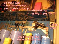
(Embarassed) I don't know how to measure the voltage of the 5651 tube to see if it is correct (pins?)
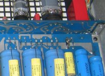
I have attached a couple pictures. One shows the "temporary" set up the 2 resistors replacing the burned one, including that it goes to pin 7 of v7. Also shown is where I measured around the "can" and am getting a reading of around 6 volts which if I am measuring correctly may be out of the recommended range? Also showing the 2 resistors paralled to the "can".
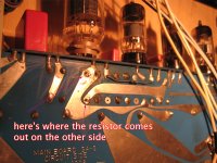
Am totally lost trying to trace? I need a GPS! I have attached a photo of the other side of the board showing where the replaced resistor leads come out. Now knowing the value of the resistor, maybe I don't need to do any more tracing? If not, I will take a few breaths and give if another whirl I necessary?
Thank you sooo much for all this input.
Ed
Hi All,
Sorry for late return. Had to get some brownie points around the house first...
Thank you for the in-depth information. One of the most interesting things I am learning is as things age, an identical part swap may not be the best thing to do. Instead use parts as required to have the end result meet spec. Unless of course you do a total rebuild with all new parts from scratch!
Good to know that it is better for the 5651 tube to take longer than shorter to turn on. I may even try building the "relaxation oscillator".
I am going to replace the resistors as recommended and appreciate all the variations to consider for best results.
I must admit this is the first time I have ever measured anything while "on" and appreciate the heads-up regarding voltages. The only thing I do that comes close is biasing tubes in my power amp... and ooh boy... touching the wrong thing even with my DVM leads is an eye opener.
(Embarassed) I don't know how to measure the voltage of the 5651 tube to see if it is correct (pins?)
I have attached a couple pictures. One shows the "temporary" set up the 2 resistors replacing the burned one, including that it goes to pin 7 of v7. Also shown is where I measured around the "can" and am getting a reading of around 6 volts which if I am measuring correctly may be out of the recommended range? Also showing the 2 resistors paralled to the "can".
Am totally lost trying to trace? I need a GPS! I have attached a photo of the other side of the board showing where the replaced resistor leads come out. Now knowing the value of the resistor, maybe I don't need to do any more tracing? If not, I will take a few breaths and give if another whirl I necessary?
Thank you sooo much for all this input.
Ed
Attachments
Hi Ed,
It's best to simply measure the output voltage. The voltage regulator tube is a higher impedance point and may be sensitive to added capacitance. The effect your meter will have would be a momentary drop in supply voltage as your meter charges up. You really don't want to do that, do you?
I'll have to look at one to figure out that resistor value for you. Anyone who knows off-hand is free to chime in here, I can't remember.
So unless there is a compelling reason to do anything else, try to maintain the device as designed. Most engineers have done an excellent job, except for "the others".
-Chris
It's best to simply measure the output voltage. The voltage regulator tube is a higher impedance point and may be sensitive to added capacitance. The effect your meter will have would be a momentary drop in supply voltage as your meter charges up. You really don't want to do that, do you?
I'll have to look at one to figure out that resistor value for you. Anyone who knows off-hand is free to chime in here, I can't remember.
I disagree, unless the original design was not well done. You want to replace parts with exact or close substitutes. If other parts have drifted with age, they require replacement as they are defective (by definition).One of the most interesting things I am learning is as things age, an identical part swap may not be the best thing to do. Instead use parts as required to have the end result meet spec.
So unless there is a compelling reason to do anything else, try to maintain the device as designed. Most engineers have done an excellent job, except for "the others".
-Chris
Hi All,
(Embarrassed) I don't know how to measure the voltage of the 5651 tube to see if it is correct (pins?)
Ed
Don't be. It is always a good idea to ask before poking around a working high voltage circuit.
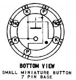
You can measure the 5651 valve plate to cathode voltage directly, provided that you have a high impedance voltmeter. A typical DVM will be 10M or more. If your DVM not auto ranging, select a setting that allows for 300V.
The base pinout is attached. Measure between P and K. The reading should be 85-86V
Attachments
Hi Alan,
Thanks for posting the pinout.
If you have an auto-ranging DMM, you'll want to put it into manual and at the correct range. The loading can cause really large spikes in the output of the regulator in auto mode, repetitive spikes as the meter adjusts it's range. Also, it depends on the input capacitance and coupling of signals. Since this is the reference to an active amplifier, you want to take more care probing around. If you are unlucky, you can cause an oscillation that then causes other components to fail.
I strongly recommend that you measure the output of the regulator and go from there. If it's correct (in the right range), you don't have to poke around the reference.
There are 499 ohm resistors in series with the different sections, so if you lose B+, check those first. Also, don't run the unit with any tubes removed. There are some models where the plate coupling capacitors are not rated at a high enough voltage. No tube means no current draw. That impresses the full B+ voltage across the coupling capacitor. Not good.
-Chris
Thanks guys! I shall move along slowly, carefully and make sure I am using the appropriate equipment. You'll laugh with me at this... my replacement resistors just showed up today. I did go with the larger wattage versions without actually looking at what size they are spec'd at. Cripes, the 49k9 is size of a small tootsie roll, and the 23k7 is like a firecracker! Oh my this is too funny. I might give them a whirl temporarily, but will likely reorder just a wee bit smaller.
All of this information is so appreciated. Afraid my business workload has me, well overloaded. Hopefully can get to poking around some more around Christmas.
Thanks for staying in touch.
Best Regards,
Ed
All of this information is so appreciated. Afraid my business workload has me, well overloaded. Hopefully can get to poking around some more around Christmas.
Thanks for staying in touch.
Best Regards,
Ed
Thought Victorious, But Back In Trenches
I've reorded some smaller resistors for better fit. Though sticking to decent grades like Caddock and Holco.
Along with the first batch of resistors, I also ordered some Photo Flash Capacitors. This is what had been running in the unit since mid eighties or so. (I had had a problem back then, and the gentlemen who sold me the preamp was a service guru as well. He siuggest replacing the 2 100 uf cans with 4 200 uf Photo Flash. 2 for each side as it were.)
So one of the other things I thought I could replace on the cheap were the caps. The minute I tacked together a quick set up, I couldn't believe how quickly the 5651 came on. Woo hoo. I was going to post right away, but figured I would neatly assemble everything back together.
Wanting to work on it right away, I drained the caps with a 1M ohm resistor as I had read best to drain before tinkering around. Well, once everything was tucked back in, dang, now the 5651 again takes a few minutes before it comes on. I thought maybe I had destroyed the photoflash caps with my draining method, but as I always buy extras, quickly set some more up again. (I am running outboard caps next to my power supply on a piece of plywood! Look like a made scientist!). Result was no different, but at least the 5651 eventually comes on.
The only thing I am noticing now is, if I turn the preamp off, then on again, the 5651 strikes almost instantly. But not if left off for awhile.
The other thing happening is my 6JC6A's aint to happy about all this. Sometimes they glow really bright before they settle in. If they don't settle in, I test them, and they are definitely getting worn out by something, and need to be replaced. Have stocked up on them!
I did check the output voltage of the 5651, am getting a reading of 84.2 volts.
Thanks for the pin out chart.
I'll be darned now if the green light on the power supply does't seem to be glowing as bright as I remember. I usually quite anal about those things. Could be my imagination, but still doesn't seem right. Don't know if that means anything. Might start poking around some of the resistors in there.
I must admit I am getting close to fealing defeated.
I think I have to go back and check some of the other suggestions.
I wish I could do things more step by step, but I don't think I have enough knowledge for that.
But at least I have music! Not going to send to service just yet.
Best of the season to all.
Ed
- Status
- This old topic is closed. If you want to reopen this topic, contact a moderator using the "Report Post" button.
- Home
- Source & Line
- Analog Line Level
- Counterpoint SA5 Preamp Problem