Hi Chris,
Will check out the current regulator when all back together.
I honestly don't think it will take that long to reassemble. I've cleaned/removed all the excess solder on all joints simply by heating and blowing it off into a wet cloth with a can of air. Really fast and left clean results!
Found some "gunk" between the areas that I spotted the sparks. The traces in that area are fairly close together. Maybe was shorting? Arcing? Hence the smell? Cleaned that up as well.
The 6JC6A that failed just read in the replace zone on my B&K 700. Previous tubes I replaced had read "short". So I guess it was on it's way? It was reading a strong 90 when I put it in. (I bought a bunch of these to have on hand as spares).
Some of the traces have lifted slightly. I don't know if there is an adhesive to flatten them. Will do some research. Once the boards are back together tight, may not make a difference.
Chris, Thanks for the therapy and advice!
Everything went back together nicely. I had carefully clamped the boards for a snug fit. Any of the lifted traces flatten into place when the 2 boards are tight to each other so didn't appear to be an area of concern.
For each joint I use just a minimum amount of WBT solder with just a microscopic amount of old Kester solder paste that I've had for years. The joints are beeeeuuutiful.
So far been running all week without any problems.
Am getting a reading of 42 volts across the the current regulator. So hoping it was the bad connections that was causing 6JC6A failure.
Gonna let things run like this for awhile, listen to some music, then get back to replacing the photoflash caps and a few other temporary resistors.
Hi Ed,
That's great!
The voltage across the current regulator diode is just about perfect, but you will see it changes as your AC line voltage changes. It appears as though your power supply is now happy.
The 6JC6A failures have me worried. A drop in transconductance (or emission on your B&K) for short service is a big warning sign for me. The shorted tubes are even more worrisome. Can you tell me which elements measure short please? Those photo-flash capacitors should be replaced at your earliest opportunity, like in a couple days as in how long it takes Digikey, Mouser or Newark to ship to you. Use the original axial lead type capacitors, I got one preamp in where the guy used radial types, and some other bad practices. Don't do work like that.
The deposits on the PCB should always be removed, so good going there. I use lacquer thinner and a toothbrush for this. Clamping the traces onto the PCB with glue is fine, but doesn't work where there are solder areas. "Super glue" makes nasty fumes when heated, and I think they all do. You should be fine. These days I use silicone to tack loose traces down. No worse than cutting them out and using wire, and neater as long as the copper is in good condition.
Back to your 6JC6A issue.
Can you make the room dark and watch the tube carefully as you turn the preamp on and off. Watch for sparks or blue flashes within the elements. You may need to view down from the top area of the tube to see inside. Repeat a couple times from a discharged state so you don't miss anything.
-Chris
counterpoint pics caps
Hi Chris,
I thought I would send you pics of where I am using the Photoflash caps as I believe at some point I may have misinformed you where they were going.
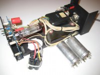
The original caps in the PS were the "can style" as shown.
It was within a few years of my purchase of the preamp that the cans were replaced with Photoflash caps. You can see where they were siliconed to the bottom of the PS. (A group of 4 caps in a plastic cup!) As mentioned before the Photoflash caps lasted a good 15 or more years.
As mentioned before, once I started having problems with the preamp I figured those Photoflash caps should be replaced with a new set. Realizing now that is a "no no" I will replace them with caps recommended in previous posts.
Now knowing which caps I am replacing I believe it is "radial" that I need, correct?
.......................
I have retested the 6JC6A currently in the preamp and it is strong as ever. I don't see any arcing in the dark when I turn the preamp on, but will keep a close watch on it. I don't think I have had the cover back on since this whole affair started. Sheesh.
Of the 5 that I put through torture, 2 read outright short and the other 3 in the replace/reject zone on my tester. I did try looking at them all in the dark while testing them to see if I could spot something. Nothing that I could identify unfortunately.
Might I be able to use a DVM between different pins while they are out to give me short results?
Check out the pic with the submarine and barge size resistors. I laugh each time I see them!
Thanks again for your help!
Ed
Hi Chris,
I thought I would send you pics of where I am using the Photoflash caps as I believe at some point I may have misinformed you where they were going.
The original caps in the PS were the "can style" as shown.
It was within a few years of my purchase of the preamp that the cans were replaced with Photoflash caps. You can see where they were siliconed to the bottom of the PS. (A group of 4 caps in a plastic cup!) As mentioned before the Photoflash caps lasted a good 15 or more years.
As mentioned before, once I started having problems with the preamp I figured those Photoflash caps should be replaced with a new set. Realizing now that is a "no no" I will replace them with caps recommended in previous posts.
Now knowing which caps I am replacing I believe it is "radial" that I need, correct?
.......................
I have retested the 6JC6A currently in the preamp and it is strong as ever. I don't see any arcing in the dark when I turn the preamp on, but will keep a close watch on it. I don't think I have had the cover back on since this whole affair started. Sheesh.
Of the 5 that I put through torture, 2 read outright short and the other 3 in the replace/reject zone on my tester. I did try looking at them all in the dark while testing them to see if I could spot something. Nothing that I could identify unfortunately.
Might I be able to use a DVM between different pins while they are out to give me short results?
Check out the pic with the submarine and barge size resistors. I laugh each time I see them!
Thanks again for your help!
Ed
Attachments
Hi Ed,
That poor, defenseless preamplifier! It seems to be in good hands now as you represent a restoring force. I can only assume that the previous work was done with the intentions of improving it in some way. BTW, the leads that run from the PCB to the group of radial capacitors would have reduced any possible improvement to zero or below.")
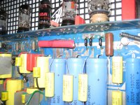
I don't see any "photo-flash" capacitors in either of your pictures. I do see a pair of orange coloured capacitors that I don't like the looks of. Put those on the list as well. The aluminum cans are called "can capacitors", or "multi-section can capacitors". The others there are "radia"l types, the leads attach off axis on one end, or radially. The picture of the audio chassis show what are called "axial capacitors", the leads attach along the axis of the part.
I have some medical stuff to do, but when I get back I'll have a look at a stock SA-5 to refresh my memory. I'm hoping to give you some direction. Remember, the best parts for the job are the ones that fit. Tell me, why was the resistor replaced on the main PCB? I'm going to strongly recommend that be returned to normal as well. This type of service you don't need in anything you're going to keep.
The situation with the 6JC6A needs clarification I think. It appears as though someone was having problems figuring out a power supply issue in the past. It's at that time that the 6JC6As may have been abused. Just a thought.
See the rectifier tube in the power supply? I think there may be issues with PCB tracking and shorting in that area. Since you will be replacing parts on that board, at the same time you should do this work. Pull the tube socket and locate the traces for the heater. Cut those traces at both ends so they are not connected to anything, then run wires from the heater attachment locations (from the transformer) directly to the pins on the socket, or the traces directly at that location. This will eliminate that problem. If you should see any evident that tacking may have occurred, remove the tracks with a dremel tool or knife. If you remove a lot of material, replace it with epoxy (not the conductive type!!). I have had to cut away right through the PCB to remove the carbonized areas of circuit board. Then the hole was filled with epoxy. I used oiled plastic panels (old CD case) sections to support the epoxy and give it a flat finish. Once the plastic was removed, the patch only required a little detail work. This is the same method used on Bryston 4B PCBs and a few others that decided to burn right through.
When you are done, the board and components should look close to factory condition with components seated properly on the PCBs. There are reasons for this, and reliability is one of them.
-Chris
That poor, defenseless preamplifier! It seems to be in good hands now as you represent a restoring force. I can only assume that the previous work was done with the intentions of improving it in some way. BTW, the leads that run from the PCB to the group of radial capacitors would have reduced any possible improvement to zero or below.
I don't see any "photo-flash" capacitors in either of your pictures. I do see a pair of orange coloured capacitors that I don't like the looks of. Put those on the list as well. The aluminum cans are called "can capacitors", or "multi-section can capacitors". The others there are "radia"l types, the leads attach off axis on one end, or radially. The picture of the audio chassis show what are called "axial capacitors", the leads attach along the axis of the part.
I have some medical stuff to do, but when I get back I'll have a look at a stock SA-5 to refresh my memory. I'm hoping to give you some direction. Remember, the best parts for the job are the ones that fit. Tell me, why was the resistor replaced on the main PCB? I'm going to strongly recommend that be returned to normal as well. This type of service you don't need in anything you're going to keep.
The situation with the 6JC6A needs clarification I think. It appears as though someone was having problems figuring out a power supply issue in the past. It's at that time that the 6JC6As may have been abused. Just a thought.
See the rectifier tube in the power supply? I think there may be issues with PCB tracking and shorting in that area. Since you will be replacing parts on that board, at the same time you should do this work. Pull the tube socket and locate the traces for the heater. Cut those traces at both ends so they are not connected to anything, then run wires from the heater attachment locations (from the transformer) directly to the pins on the socket, or the traces directly at that location. This will eliminate that problem. If you should see any evident that tacking may have occurred, remove the tracks with a dremel tool or knife. If you remove a lot of material, replace it with epoxy (not the conductive type!!). I have had to cut away right through the PCB to remove the carbonized areas of circuit board. Then the hole was filled with epoxy. I used oiled plastic panels (old CD case) sections to support the epoxy and give it a flat finish. Once the plastic was removed, the patch only required a little detail work. This is the same method used on Bryston 4B PCBs and a few others that decided to burn right through.
When you are done, the board and components should look close to factory condition with components seated properly on the PCBs. There are reasons for this, and reliability is one of them.
-Chris
Preamp on the mend
Hi Chris,
(Preamp part)
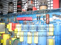
I replaced the 49k9 resistor (big brown one) as it was definitely showing signs of deterioration. Recommended in the threads was to also replace the 23k7 as well. Advice was to use as high wattage as possible for heat dissipation. Geeze I didn't realize how big the resistors were until I received them. Guess I went overboard. But they did fit. I do have Holco equivalents though not that high wattage. Perhaps I should look for something midway...
(Power supply)
I'm not sure if the orange pair of resistors you see in the power supply are the blackgates I put in when the original resistors burned out. They are equivalent in value to what was in there before. Hope okay?
The quad of caps you see attached by wires and currently sitting outside the power supply are Rubicon Photoflash. Guess these are the ones I should start with replacing pronto!
Hope all goes well with your medical treatment.
Thanks again for all your help.
Will try not to blow things up before you return. No promises though!
Take Care,
Ed
Hi Chris,
(Preamp part)
I replaced the 49k9 resistor (big brown one) as it was definitely showing signs of deterioration. Recommended in the threads was to also replace the 23k7 as well. Advice was to use as high wattage as possible for heat dissipation. Geeze I didn't realize how big the resistors were until I received them. Guess I went overboard. But they did fit. I do have Holco equivalents though not that high wattage. Perhaps I should look for something midway...
(Power supply)
I'm not sure if the orange pair of resistors you see in the power supply are the blackgates I put in when the original resistors burned out. They are equivalent in value to what was in there before. Hope okay?
The quad of caps you see attached by wires and currently sitting outside the power supply are Rubicon Photoflash. Guess these are the ones I should start with replacing pronto!
Hope all goes well with your medical treatment.
Thanks again for all your help.
Will try not to blow things up before you return. No promises though!
Take Care,
Ed
Attachments
Hi Ed,
Yes, the parts in the power supply. Those are capacitors, aren't they?
Once a part becomes too large for the space, it also becomes a liability. What they should have told you about resistors is that you should only ever need to go up one wattage size. You can easily find out what your actual dissipation is. Measure the voltage across the part, then figure out the current flowing through the part. Multiply the current by the voltage and you have your dissipation. Oversizing by a factor of three or a little more should be just fine. Certainly, make sure the parts do fit. If they don't, get one that does.
Those 1% parts are completely wrong. Use 5%, Metal Oxide resistors. They will be much, much smaller. What you have installed there is a complete waste, plus they don't fit. What you see there is a great example of what not to do. I have to say that those resistors were probably expensive, but inferior in that application to the Metal Oxide types.
Black Gate caps .... In my view, a total waste of money. Find something that fits the mounting location.
-Chris
SIY Asylum
Thanks Chris,
I ordered those resistors to match the needed values, without checking the size. Lesson learned! They weren't expensive. Shipping was more.
I had nothing else to put in there, other than doubling up of some low wattage smaller resistors temporarily to match required values.
Oh Boy. It's Screw-It-Up Yourself Asylum for me!
Will fix those up as recommended.
Again, thanks for all your help.
Regards,
Ed
Hi Anatech. I was going to start a new thread before seeing this one. I had an Sa5 in perfect woring order till I got my mitts inside it. I was alwways bothered by the volume control, which always tracked poorly, and ordered a new Audio Note 100K to replace it. I also thought it would be a good idea to bypass the gain pots. I don´t believe that the volume control caused the problem, but to remove the gaim controls, I simply connected the input lead to output. After turning it on, it worked fine at a low volume but when turned up a bit, the right channel began to cut out off and on before going altogether and the left would "bottom out" before reaching half volume. I rewired the gain controls, double checked the wiring for the volume control and installed a set of used 6922´s in the line stage to try again. The right channel is still out. I have no schematic or service manual for this and am at a loss to find the problem, save going over it part by part. Just so you should know, I´m in southern Spain where there is little to no place I could take it, and at the moment, I don´t have a tube tester.
Don
Don
Chris, Alan (et el)... just letting everyone know everything is working great. I have replaced the photoflash caps and monster size resistors.
Alan, I have sent you a PM regarding the vertical circuit board.
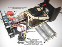
While poking around I also noticed my umbilical power cord wires were looking tattered. Especially the ones where the design called for two wires going into holes sized only for one. I re-dressed all the wiring and have attached some before and after links.
Where two wires had to fit into one small hole (two instances), I bared and crimped the wires together, leaving about 1/4" sticking out. I then soldered, and filed this portion to fit. Everything was neatly heat shrinked. On one set I used clear shrink. You can see the crimp.
You can also see in the pics the original wires that had strands cut from each lead in order to fit the small hole.
I could swear I hear a larger sound stage and overall power after I re-dressed all of these wires. Though by the time I finished this, it was very late in the evening... and everything sounds better then...
Ed
http://dl.dropbox.com/u/5444992/IMG_0034.JPG
http://dl.dropbox.com/u/5444992/IMG_0038.JPG
http://dl.dropbox.com/u/5444992/IMG_0048.JPG
http://dl.dropbox.com/u/5444992/IMG_0055.JPG
http://dl.dropbox.com/u/5444992/IMG_0060.JPG
Alan, I have sent you a PM regarding the vertical circuit board.
While poking around I also noticed my umbilical power cord wires were looking tattered. Especially the ones where the design called for two wires going into holes sized only for one. I re-dressed all the wiring and have attached some before and after links.
Where two wires had to fit into one small hole (two instances), I bared and crimped the wires together, leaving about 1/4" sticking out. I then soldered, and filed this portion to fit. Everything was neatly heat shrinked. On one set I used clear shrink. You can see the crimp.
You can also see in the pics the original wires that had strands cut from each lead in order to fit the small hole.
I could swear I hear a larger sound stage and overall power after I re-dressed all of these wires. Though by the time I finished this, it was very late in the evening... and everything sounds better then...
Ed
http://dl.dropbox.com/u/5444992/IMG_0034.JPG
http://dl.dropbox.com/u/5444992/IMG_0038.JPG
http://dl.dropbox.com/u/5444992/IMG_0048.JPG
http://dl.dropbox.com/u/5444992/IMG_0055.JPG
http://dl.dropbox.com/u/5444992/IMG_0060.JPG
Hi Anatech
I have a Conterpoint SA-5.1 and i am looking at 2 resistors values: located between the 6GC5 tube and the big red capacitor ( 1 UF ) on the vertical pc board.
These resistors are connected on the filament heaters and i don't know where.
They are burned.
If you can tell me the values, it will be appreciated!
By the way, is your schematic available?
Thanks
If you mean the heater supply for V7 (6GC5) & V8(6CA4) then these are both 10k 0.5W 1% resistors. They connect each 'side' of the 6.3VRMS filament supply to the +260V output voltage of the B+ regulator.I have a Conterpoint SA-5.1 and i am looking at 2 resistors values: located between the 6GC5 tube and the big red capacitor ( 1 UF ) on the vertical pc board.
These resistors are connected on the filament heaters and i don't know where.
C55/C57 and C58 are the axial leaded electrolytic caps that decouple the second stage phono, and line stage A & B, respectively. These are 200uF/250V and they have 250V across them. Good eh? Replace with the next available voltage rating - probably 385V/400V.
Hi, I want to replace these electrolytic caps with film caps. The bigger caps are 200uf - 250V and the smaller ones on their top are 0.47uf - 210V. Up to this thread I thought that 0.47uf's are what I need (to replace the whole). But I'm confused now, what caps should I buy?
Attachments
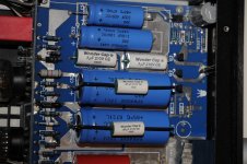
The big blue Sprague 1501s are electrolytic capacitors.Hi, I want to replace these electrolytic caps with film caps. The bigger caps are 200uf - 250V and the smaller ones on their top are 0.47uf - 210V. Up to this thread I thought that 0.47uf's are what I need (to replace the whole). But I'm confused now, what caps should I buy?
The white Wondercaps are film caps.
If you replace any of the power supply capacitors, you need to choose capacitors with a voltage rating greater than 260V, preferably greater than 300V to give you a safety margin. The original capacitors in this unit run at or below their rated voltage which is not best practice
Thank you for your help, but l'm afraid l need more.
ln some photos of upgraded SA-5.1 units l see caps like 150uf - 350V and no 0.47uf's. What's the purpose of 0,47uf's?
AFAlK, in the original design C55, C57 and C58 are identical caps. But after upgrade my C55 cap is something like 8uf - 415 (not sure, since writing this message from mobile). Not 150uf, not 0.47uf. So l'm confused
No problem, I understand what you are looking for now.Thank you for your help, but l'm afraid l need more.
The 0.47uF are film caps which bypass the electrolytic caps. The aim is to improve the high frequency performance of the bypass. Depending on the actual choice of parts this may or may not be true in practice.ln some photos of upgraded SA-5.1 units l see caps like 150uf - 350V and no 0.47uf's. What's the purpose of 0,47uf's?
It is understandable that you are confused. Whoever 'upgraded' your preamplifier did not use the original value parts. This is usually done because the part fitted is all that was available at the time and it fits the chassis. If I was cynical, I would then say that the change in value is then justified by some nonsense about how it is an 'upgrade'.AFAlK, in the original design C55, C57 and C58 are identical caps. But after upgrade my C55 cap is something like 8uf - 415 (not sure, since writing this message from mobile). Not 150uf, not 0.47uf. So l'm confused
In the original C55, C57 & C58 are all Sprague 200uF/250V caps. The voltage rating was inadequate as the B+ rail sits at +260V and often higher at startup. Although under-rated, the caps are of good quality so they do take a while to die. If you are replacing them, then choose an axial leaded electrolytic, rated at 300V or higher, of a suitable size.
I do not have a SA5 anymore, so if you measure the cap size then I could make a suitable recommendation.
Each of the electrolytic caps (C55/57/58) were bypassed by 1uF/200V Wondercaps (C59/60/61 respectively). Again the voltage rating is too low, so if you are replacing these caps then choose something with a voltage rating > 300V.
- Status
- This old topic is closed. If you want to reopen this topic, contact a moderator using the "Report Post" button.
- Home
- Source & Line
- Analog Line Level
- Counterpoint SA5 Preamp Problem