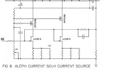
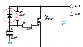
Mr. Pass, can you tell me if the THD lowers without the use of the C1 cap (10.000uF) ? (This will mean that the PSU will have +Vcc and -Vcc )
Have you tried this solution ?
( the problem is to correct the offset of the amp without feedback... )
thanks
Edit: And why not a non polarized cap ?
Have you tried this solution ?
( the problem is to correct the offset of the amp without feedback... )
thanks

Edit: And why not a non polarized cap ?
I received at note from Alex (X-pro) pointing out his post:
http://www.diyaudio.com/forums/showthread.php?s=&threadid=48500&perpage=10&pagenumber=1
http://www.diyaudio.com/forums/showthread.php?s=&threadid=48500&perpage=10&pagenumber=1
Mr. Pass, thanks for your reply.
And if I would lower the voltage to get a higher bias current at the same heat dissipation, does this affect the non-linearity as much as with the Aleph amps? I read you didn't like to go much below 25 volts (+ and - each) because of these non-linearities due to the capacitance.
And if I would lower the voltage to get a higher bias current at the same heat dissipation, does this affect the non-linearity as much as with the Aleph amps? I read you didn't like to go much below 25 volts (+ and - each) because of these non-linearities due to the capacitance.
Hi there!
I finished my ZEN V8 yesterday. It had been working with mosfets. However, since I obtained Jfets recently (thanks Grey!) I did a "proper" one, as described in the article.
Current is supplied by 1500w 220w halogen sticks in parallell with 75 Ohm resistor. Power supply: passive CLCRC filtering. 46 V.
I had to increase the value of R1 to 0.69 Ohm (0.47+0.22) in order to get 1.1 v at the Source of Jfet. On its drain I measured 2.25 V. On the source of Q2 I set 23 V (half supply) via P1.
Sounds nice. There is one interesting thing, however. I preferred
the sound without feedback. With 47k and 4.7 K resistors in place, it has less gain, sounds more "polite" and "solid" but apparently looses some "air" and "liveness" . So now I am experimenting with the amount of feedback. I am thinking to lower 4.7K resistor to 2.2 K or 1.5 K. Input impedance is not a problem, I am running it with BOZ...
Any feedback about feedback?
Best regards,
Vix
dr.strangelove3 said:And if I would lower the voltage to get a higher bias current at the same heat dissipation, does this affect the non-linearity as much as with the Aleph amps? I read you didn't like to go much below 25 volts (+ and - each) because of these non-linearities due to the capacitance.
This circuit likes voltage even more, since it has losses due to
cascoding.
Vix said:Sounds nice. There is one interesting thing, however. I
preferred the sound without feedback.
Not uncommon. There are two easy reasons - 1) No feedback
sounds different all by itself, and 2) the output impedance will
be very much higher, eliciting a different response from the
speaker. If you haven't seen it, check out the article on
current source amps and efficient full range speakers at
www.firstwatt.com
Thanks for you reply Mr. Pass,
So lowering the voltage isn't such a good idea...
And if used a mosfet in the cascode that is meant to operate at lower voltages like the irfp044 or irfp064n?
These devices should be more linear at lower voltages.
And the input capacitance of these mosfets (especially the irfp064n with 4000pF), is this of any influence in your cascode design?
Thank you very much Mr. Pass!
Yes, I have read the article. I have done some experimenting with the amount of feedback. It seems that I prefer "just a little bit of feedback". With no feedback, it sounds "loose" and on a higher volume I get an impression that the speaker cone does "uncontrolled" movements, but the midrange is very sweet and and overall sounds more detailed.
On the other hand, with feedback implemented, bass gets tighter, but something gets "killed", the sweetness is gone, sounds dry...
Nevertheless, I tweak the amount of feedback by varying the value of resistor R7 (originally 4.7 k) while R6 remains at 47 K.
Now, the question is: If I implement just a small amount of feedback (R7 at 2.2 K) will it then act more like voltage, or like current (transconductance) amplifier?
Thanks a lot,
Vix
p.s. these amps are such a good toys, aren't they?
Well I have a week vacation so I will make a start on this project
On the transformer my calculations are 38 volts ac secondary/300 va.
I allowed 50volts plus 3volts for ripple and rectifiers divded by 1.4 . In Duncans simulator it came out very close 50.5volts with 30,000 mf using a 25 ohm load.
Unless anyone has any reservations that is what I plan to order.
From what I can see it is better to err on the higher than the lower side for voltage with mosfets.
Perhaps the Master can confirm
Ian
You can't make volts out of nothing, but if you've got too many you can always burn them off with resistors, regulators, whatever. As long as you've got the heatsinking, you'll be okay.
Note that the simulations will probably be wrong. I've got power transformers that deliver a volt or two more than they're rated for, even when faily heavily loaded. I've got others that deliver less.
A volt or two here or there won't break the circuit, regardless.
Grey
Note that the simulations will probably be wrong. I've got power transformers that deliver a volt or two more than they're rated for, even when faily heavily loaded. I've got others that deliver less.
A volt or two here or there won't break the circuit, regardless.
Grey
Yes, the boards are available now.
A set of PCBS (2 amp boards and two PS boards) is $20, shipping $8. Each additional set is $2 extra for shipping. Boards are being shipped directly from Poland.
Please e-mail me for payment details (message subject Zv9).
More info here: http://www.diyaudio.com/forums/showthread.php?postid=920451#post920451
XELB said:As any one tried the Zv9 at +42 V ?
Does it need any change ?
Thanks guys.
Where is the +42V . . . ?
It replaces the original +50V . . . ?
Connect +42V.
Adjust P1 from start point of 5K slowly up to until you see 7V across P1.
And, live with it . . .

- Status
- This old topic is closed. If you want to reopen this topic, contact a moderator using the "Report Post" button.
- Home
- Amplifiers
- Pass Labs
- Zv9

