RoboMan said:Smart move. But stupid questions are difficult to create! What do you teach, hopefully not electronics!
Thanks for the explanation. You have cleared it up for me - the books Choky sent me assume some knowledge that I do not have...yet.
How to navigate their way through a mainframe... training, more than teaching. But, wouldn't I be perfect for electronics -
"He who can, does. He who cannot, teaches."
--G.B. Shaw, "Maxims for Revolutionists" in Man and Superman (1903)
Cloth Ears said:
How to navigate their way through a mainframe... training, more than teaching. But, wouldn't I be perfect for electronics -
"He who can, does. He who cannot, teaches."
--G.B. Shaw, "Maxims for Revolutionists" in Man and Superman (1903)
I should be teaching mainframe then!
I appreciate all your patience...
A couple of other questions (seemingly, completely unrelated) spring to mind along with my reading - isn't it amazing that the more you know, the more you find you don't know (and need to)?
Firstly, if you decide to load the outputs with inductance to the positive rail (ZV7-T), and you use 2 parallel secondary windings of an AC power transformer - what do you do with the primary winding? Do you short it out (join the ends) or do something else with it? Does it matter?
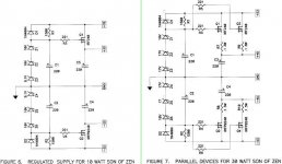
Secondly, (I'm leaping all over the place here), in the write up for Zen Variations Part 3 (Active Supply Regulation) there are 2 schemas for regulation for Son of Zen - in figures 6 and 7 (attached). If you set up the supply as in figure 7 (allowing for 50+ volts rails), can you 'simply' alter the output voltage by changing the number or value of the zener diodes in the circuit? Also, is it worthwhile having big capacitors after the regulation circuit, or is it just a waste of space (money, et al)?
OK. It ended up being more than 2 actual questions, but...
A couple of other questions (seemingly, completely unrelated) spring to mind along with my reading - isn't it amazing that the more you know, the more you find you don't know (and need to)?
Firstly, if you decide to load the outputs with inductance to the positive rail (ZV7-T), and you use 2 parallel secondary windings of an AC power transformer - what do you do with the primary winding? Do you short it out (join the ends) or do something else with it? Does it matter?
Secondly, (I'm leaping all over the place here), in the write up for Zen Variations Part 3 (Active Supply Regulation) there are 2 schemas for regulation for Son of Zen - in figures 6 and 7 (attached). If you set up the supply as in figure 7 (allowing for 50+ volts rails), can you 'simply' alter the output voltage by changing the number or value of the zener diodes in the circuit? Also, is it worthwhile having big capacitors after the regulation circuit, or is it just a waste of space (money, et al)?
OK. It ended up being more than 2 actual questions, but...
Attachments
Cloth Ears said:
Firstly, if you decide to load the outputs with inductance to the positive rail (ZV7-T), and you use 2 parallel secondary windings of an AC power transformer - what do you do with the primary winding? Do you short it out (join the ends) or do something else with it? Does it matter?
You can leave the primary un-connected unless you want to take the output from the primary (usually for used for long distance connection such as a PA system and you have to use a step-down transformer at the other end to drive a low impedance speaker).
Secondly, (I'm leaping all over the place here), in the write up for Zen Variations Part 3 (Active Supply Regulation) there are 2 schemas for regulation for Son of Zen - in figures 6 and 7 (attached). If you set up the supply as in figure 7 (allowing for 50+ volts rails), can you 'simply' alter the output voltage by changing the number or value of the zener diodes in the circuit? Also, is it worthwhile having big capacitors after the regulation circuit, or is it just a waste of space (money, et al)?
Unless you are using very sensitive speakers (> 95db/w/m), I don't think it is necessary to use regulated power supply for a power amp. A C-L-C filter is usually good enough. If I were you, I'll try a simple power suppy first and add regulators later if necessary.
Of course it is possible to increase the output voltage by changing the number of zener diodes. But for a regulator, the input voltage must be a few volts higher than the output voltage so that "regulation" can be maintained.
If you are raising the supply voltage, you'll better keep the dissipation of each MOSFET within the 50W limit (even though the Pc of IRFP240 is 150W, max. 30W per MOSFET is recommended).
If you are using active regulator, you should not put big caps after regulation because they may drop high current at start up and may damage the regulator. However, you may put a small cap like 220uF and a 0.1uF film caps on the PCB to improve high frequency performance (220uF is already in the circuit).
Hope this answers your questions.
RoboMan said:Unless you are using very sensitive speakers (> 95db/w/m), I don't think it is necessary to use regulated power supply for a power amp. A C-L-C filter is usually good enough. If I were you, I'll try a simple power suppy first and add regulators later if necessary.
Hope this answers your questions.
Sure does.
The drivers (active x-over) I was looking at are 100dB/W/m - either the tweeter or the midrange. I do have existing power amps to do the job, but I've got this other stuff lying around and I thought "what the hey...". The reason I asked was that the AC transformers I have lying around are 625VA 40-0-40, and I was planning on running the amps with only about 25-30 volts max. I don't think the 625's have enough guts to run a SOZ at 55 volts.
With the "transformers as inductor" set-up as it is in ZV7-T, would there be any real AC through these loops? And, if it's only DC (or close to it), what would be the difference between shorted primary and unshorted? I'm not going to be using the primary for anything (unless I need a 35H inductor - apparently that's what it is, but I've yet to measure it).
Thanks for your help.
Cloth Ears said:
The reason I asked was that the AC transformers I have lying around are 625VA 40-0-40, and I was planning on running the amps with only about 25-30 volts max. I don't think the 625's have enough guts to run a SOZ at 55 volts.
Sure your transformers are suitable for Fig 7 of your previous posting.
With the "transformers as inductor" set-up as it is in ZV7-T, would there be any real AC through these loops? And, if it's only DC (or close to it), what would be the difference between shorted primary and unshorted? I'm not going to be using the primary for anything (unless I need a 35H inductor - apparently that's what it is, but I've yet to measure it).
I did not make any Zen with inductor loading (I prefer the Constant current version which is easier to manage). The inductor provides a low DC impedance and high AC impedance environment similar to what a constant source is providing. There should be very little AC through it (high impedance, also remember that AC signal is built up across the winding). However, if you put a load on the other winding, it becomes a transformer and AC will flow through the first winding and induce to the second winding. If you short-circuit the winding, you will make the inductor becomes a low AC impedance component resulting very little AC signal for the speaker. This is not we want - the goal is to keep the AC impedance of the inductor very high and save the AC output for the speaker (while keeping the DC resistance very low to avoid DC loss).
Here is a para. from the original Zen-V7 document:
"I tried a number of transformer primaries and secondaries, and quickly found that the low voltage secondary windings didn’t give me as much inductance as I needed, and so I concentrated on using the primary windings as my load, which worked much better. I left the secondary windings open. The example of Figure 1 and the curves which follow, Figures 9 through 14, were taken with a 300 VA Plitron toroidal transformer. I also took some data with a similar, but much larger transformer. This examples uses an off-the-shelf AC line power transformer, not at all optimized for audio work. Of course you could always go out and buy transformers actually designed for audio use, but how many of you have some nice piece of junk that you can use for free? What is surprising here is how well it works. Just shows that trying something out for the hell of it can have a good outcome."
It seems that your idea of using secondary winding is not what Mr. Pass suggested. It also seems that you may need to experiment with what you have in hand to get satisfory result (that is why I prefer constant current source which is more predictable). I think there should be discussions of Zen-V7 in this forum.
I've been reading and loosing track of the subject, with help I might add, but I just thought I'd add my 2 cents.
In a ZV7-T the idea of the chokes rather than the CCS or Aleph circuit, is to provide an AC load for the gain transistors and a minimal DC load. With minimal DC load you can come close to 1/2 the quiecent power dissipation. Or, close to doubling your efficiency.
The center tapped windings chosen would generally be the Pri windings as they provide the most inductance vs typical secondaries (As Nelson said). Basically more inductance translates to higher impeadance. Higher impeadance translates to more gain. The critical area to be concerned with is the lowest frequencies where the impeadance (AC) reduces. This means less gain at lower frequencies, and an induced roll-off depending on the value of the L and the value of the load. Transformers in the area of 250-1000VA or more seem usefull for this purpose. Inductances from 100-1000mH seem to be necessary. These are generally quite substantial in size and cost.
The DC current in the ZV7-T circuit creates an opposing magnetic field avoiding the saturation which would otherwise be a serious problem in a class A biased circuit. The important DC characteristic to look for would be the DCR of the inductor. Up to a few ohms would only waste 5-10 watts. Higher DCR would heat up the transformer and burn extra power...
RoboMan said:Sure your transformers are suitable for Fig 7 of your previous posting.
RoboMan,
I'm going to keep it simple (I'll leave out the last word
) and try to build a ZV6. I'f I'm running 45V +/- out of 'figure 7', what sort of dissipation (ie heatsinking) would I need for each of the IRFP240 or IRFP9240 in that set-up (a pair of each in parallel)?I've been working about 70W each, but then I'm probably over-estimating.
And, do these regulation transistors have to be the same model as the gain devices in the amplifier? Or could they be different (cheaper
) items like IRF540s or the like.Cloth Ears said:
RoboMan,
I'm going to keep it simple (I'll leave out the last word
I've been working about 70W each, but then I'm probably over-estimating.
And, do these regulation transistors have to be the same model as the gain devices in the amplifier? Or could they be different (cheaper
For the Amp, if the supply voltage is +-45V, current for each of Q1 and Q2 is 4.4A, each IRFP240 will dissipate about 67W (Vds = 15.2).
For the active regulation, Vds is 8V, total current 8.8A, the dissipation is about 70W (per ch). (Our calculations are exactly the same
)I think it is safe to use IRF540 and IRF9540 to replace IRFP240 and IRFP9240 in the supply regulation. But I found their prices not too much cheaper than 240/9240. As you will need to match the 240s, why not buy more and find some better matched ones for the amp and those not too matched ones for the supply?
I'm a bit concern about the dissipations of Q1 and Q2. 67W per MOSFET is too much.
You'll need big big heat sinks and big big resistors!!

RoboMan said:For the Amp, if the supply voltage is +-45V, current for each of Q1 and Q2 is 4.4A, each IRFP240 will dissipate about 67W (Vds = 15.2).
...
I'm a bit concern about the dissipations of Q1 and Q2. 67W per MOSFET is too much.
You'll need big big heat sinks and big big resistors!!
We're pretty close - I'd worked out 65W for each Mosfet - and putting each on a 0.45C sink should limit rise to about 30C.
For the heat sinks - I was looking at 800mm x 200mm of heatsinking )per channel) and can get it reasonably cheap. But it would be nice to get it in an easy to assemble box, rather than as rivetted together items. We'll see.
The resistors were going to be 50W items (4 in parallel making up each 'resistor'). Bulk buying brings these down a bit in price.
I'm still looking at a bit to complete it, but as I've already got the 33000uF caps and the toroids for it I thought that a bit extra won't matter. I suspect they will only be allowed in the house for short peroids, though. I don't think the missus will like the 'hedgehog' (echidna over here) look.
Here is my experience with Zen4:
As my speakers were only 92 dB/w/m, I'll need more power than a Zen4 normally can deliver. I was able to increase the supply to 50V with 3A bias and got about 20W output. Power dissipation for each MOSFET was about 75W. Temperature of heat sinks were about 60 deg. C. I was enjoying music for about a week.
Suddenly one day when I turned the power on, one channel was dead. It was found that one of the MOSFET was short-circuited. The source resistor was open-circuit.
After the problem was fixed, it happened again a week later for the other channel. Then I realised that I was pushing too hard and reverted it to 45V and 2.5A bias. Keeping 50W dissipation for each MOSFET is advisable.
I would recommend that you use 3 pairs of MOSFET in the power regulation (or at least save the space for 1 more pair) so that you can adjust the output voltage down a few volts if you don't need the extra output power (since you are using high efficiency speakers).
Good luck!
Thanks for the experience - it's always much more useful than just talk.
I was planning on building to be able to increase power with minimal changes, but I was going to start lower. 3 paralleled mosfets for each rail sounds a little over-the-top - but if I do want to get 30W, then I'll probably need it.
I've pretty much decided to try for a ZV6, but without anything else fancy - unless you think it's worth-while using a parallel pair of MosFETs for each output. Hmmm, should I also look at paralleing the feedback circuit - I think I'm trying to run before I can walk.
So, big trannies + big caps + 2/3 paralleled Mosfets for each rail = big power supply, mucho heatsinking for the MosFETs as well as the resistors. I'll start saving for the rest of the bits (heatsinks/FETs/resistors) and then see what questions I come up with once I'm there...
Thanks for the advice RoboMan - I'll re-open this when I'm ready to start soldering...
 ! Another dumb question.
I've had a look, and found a place to get some "cheap" matched MOSFETs (thanks to someone else asking in another thread). So before I buy I thought I'd look at the figures.
Roboman said in his previous post that he had trouble when the MOSFETs he was using were dissipating 75W. At the moment, I'm pretty close to that and I'd rather not be buying replacements all the time (cost is one issue, heart is another).
So, if I parallel 3 on each leg of of the regulated power supply, then the dissipation for each of these should be about 47W each - which I can live with. AND, if I parallel the output FETs in the circuit, then the dissipation for them should be 34W each - a much better figure.
Now I know this isn't really in the spirit of the Zen (or Son of Zen) thing - being 2 output devices - but I'd like to keep the stress on each device as low as I can. I don't like things being stressed...
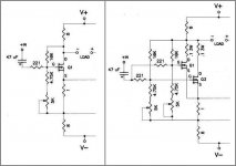
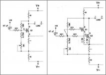
. But how do I do it?Using the + half (+IN/-LOAD) of the "FIGURE 4 SUPERSYMMETRIC SON OF ZEN" circuit from the zen-V6 article from PassDIY, I attempted to work out how to parallel the outputs. Original on the left, my feeble attempt on the right. Is this how to do it, or am I about to let out the magic smoke right at the start?
Any comments or jokes are welcome...


Attachments

Cloth Ears said:
Roboman said in his previous post that he had trouble when the MOSFETs he was using were dissipating 75W. At the moment, I'm pretty close to that and I'd rather not be buying replacements all the time (cost is one issue, heart is another).
75W for an IRFP240 is no big deal, I have to my surprise had mine running much (as in very much) harder for a year by now....
Magura
Cloth Ears said:Roboman said in his previous post that he had trouble when the MOSFETs he was using were dissipating 75W. At the moment, I'm pretty close to that and I'd rather not be buying replacements all the time (cost is one issue, heart is another).
Magura said:75W for an IRFP240 is no big deal, I have to my surprise had mine running much (as in very much) harder for a year by now....
Maybe the heatsinking wasn't as effective on Robo's FETs, and as they're only $12.40 for a matched foursome, I can probably afford the little bit extra.
Overkill, not roadkill...

 ! Or, never use 4 cylinders, when 8 will do !
Magura said:AFAIK there is no such thing as overkill when it comes to heatsinking....only limitations regarding space/cost.
Magura
I can understand why the first Pass amp I ever saw (the Aleph 3) looked like a little hedgehog, with heatsinking on all 4 sides. Because of the size of the caps and toroids I've got, it looks like I won't have any trouble with heatsinking either - IF I use the same design principle...
I hope I don't ever have to lift them in a hurry, though!
'nother dumb question
The Son of Zen schematic
shows outputs as -OUT and +OUT (and later in ZV6 it's listed as +/- LOAD). These 2 outputs connect to your speaker +/-, right?
I was looking at it and thinking, "Where's the bloody ground?"
The Son of Zen schematic
An externally hosted image should be here but it was not working when we last tested it.
shows outputs as -OUT and +OUT (and later in ZV6 it's listed as +/- LOAD). These 2 outputs connect to your speaker +/-, right?
I was looking at it and thinking, "Where's the bloody ground?"
- Status
- This old topic is closed. If you want to reopen this topic, contact a moderator using the "Report Post" button.
- Home
- Amplifiers
- Pass Labs
- Zv6-t?