Zen Mod said:...tnx to Damp Ears
I'll put myself in the clothes dryer (or hang myself out in the sun - except that it doesn't look good when I type it)...
Cloth Ears said:
I'll put myself in the clothes dryer (or hang myself out in the sun - except that it doesn't look good when I type it)...
cloth just reminds me on dampened.........not sorta wet
")
hehe-you're in better position than me.......Choky is sorta americanized
expression for 4eyes in my native..........
Attachments

I find it interesting that Walt Jung did frequency sweeps on the current sources (and sinks) he mentions in his article. I've always taken it as a given that current sources fail as the frequencies increase, so it's nice to see someone back that up with measurements.
However...
I still feel that there's more to this than he's managed to uncover so far. In my experience--and you can find posts here where I've suggested anything from around 4.75k on up--resistors still sound better in many applications, even though they may not measure as well as some of the circuits he examined.
Case in point:
In Walt's test circuit, he rates a simple 10k 1% resistor as -80dB. He then looks at various circuits, many of which measure better than the 10k resistor. I've used many (though not all) of those circuits and have found that, at least under certain circumstances, they sound worse than a resistor.
I'm going to go out on a limb here and suggest the possibility--nothing more than that at this time--that it's not so much the actual frequency performance of the circuit that influences the sound quality, but the relative flatness of the performance. In other words, does the current source treat all frequencies with an even hand?
I'm going to ponder this for a bit, but make no mistake, I think he's taken a valuable first step.
Grey
Grey,
I'll be interested to read how he fairs in his third article, when he uses some of the sources/sinks in audio circuits. Maybe he will find the measurements don't backup the sound, or that the measurements of the amp output don't backup his findings in the second article.
I must now go back to sitting and staring...!
I'll be interested to read how he fairs in his third article, when he uses some of the sources/sinks in audio circuits. Maybe he will find the measurements don't backup the sound, or that the measurements of the amp output don't backup his findings in the second article.
I must now go back to sitting and staring...
!For all that Walt suggests ignoring the "One Vbe" CCS design, I'd like to note that it shows a much flatter frequency response than many of the "better" circuits he covers later. And it's a tolerable sounding design, one I've used and listened to many times. As have many others.
No, I'm not done pondering this; just something to think about.
Grey
No, I'm not done pondering this; just something to think about.
Grey
GRollins said:In Walt's test circuit, he rates a simple 10k 1% resistor as -80dB. He then looks at various circuits, many of which measure better than the 10k resistor. I've used many (though not all) of those circuits and have found that, at least under certain circumstances, they sound worse than a resistor.
GRollins said:For all that Walt suggests ignoring the "One Vbe" CCS design, I'd like to note that it shows a much flatter frequency response than many of the "better" circuits he covers later. And it's a tolerable sounding design, one I've used and listened to many times. As have many others.
Both reasonable points. I have also encountered instances
where the dumber circuit sounded just fine.
RoboMan said:I would say that this forum is better than any book can supply. Feel free to list your questions here. (That will also benefit other people who are too shy to ask.)
Hi RoboMan,
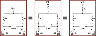
A quick question regarding the biasing resistors in ZV6 (and SOZ, I guess). Is there any reason why the attached picture would not be true? Other than the single path resistors would need to handle double the current (and dissipate twice the heat)?
You can tell I'm from passive-land...
Attachments
Cloth Ears said:
Hi RoboMan,
A quick question regarding the biasing resistors in ZV6 (and SOZ, I guess). Is there any reason why the attached picture would not be true? Other than the single path resistors would need to handle double the current (and dissipate twice the heat)?
You can tell I'm from passive-land...
in first case (most left) amplification is greatest than in case most right
Zen Mod said:
in first case (most left) amplification is greatest than in case most right
I believe you, but why? From a passive (no, not that way!) viewpoint, I see that each 'leg' has 8 ohms resistance (8 / 8, or 4+4 / 4+4, or 6+2 / 6+2).
Any help in how the electrons and anti-electrons flow will be of help.
Cloth Ears said:
I believe you, but why? From a passive (no, not that way!) viewpoint, I see that each 'leg' has 8 ohms resistance (8 / 8, or 4+4 / 4+4, or 6+2 / 6+2).
Any help in how the electrons and anti-electrons flow will be of help.
output voltage across + and - terminals is created across load resistors;
in first case that is 8+8 ohms ;
in last case that is 2+2 ohms ;
for same current (AC,off course) there is 4 times less output voltage
besides that; in middle ase is introduced sorta tail resistor and that amp became sort of LTP differential stage ......comparing to left case,that resistor helps in maintaining better balance between halves.
in right case that resistor is increased,so balancing effect is even bigger.........
one can build all 3 iterations to choose what's best for him.
hehe,and with several possible iterations,including CCS somewhere.......susy etc..........
Cloth Ears said:I will sit and contemplate a while in an attempt to grok this.
just imagine it as seesaw , hanged on rope .
what matter is just length of seesaw (ohms ) not rope (also ohms)
Zen Mod said:just imagine it as seesaw , hanged on rope .
what matter is just length of seesaw (ohms ) not rope (also ohms)
So... if we just use 16 + 16 in case 1 (left example) then output voltage is 2 times more for same current?
But, is not this part of ZV6 (V+) supposed to be DC (or at least close to) from the power supply?
Cloth Ears said:
So... if we just use 16 + 16 in case 1 (left example) then output voltage is 2 times more for same current?
yes,but you must think of output impedance,too..........and it is related to load resistance,besides everything other
But, is not this part of ZV6 (V+) supposed to be DC (or at least close to) from the power supply?
yes,so?
http://www.passdiy.com/amps.htm .......mucho pdfs for read
also
http://www.passlabs.com/articles.htm ...........but you must search for Papa's article about discrete OP..........I dunno where is it now .........aha....google...........there is it :
http://ecow.engr.wisc.edu/cgi-bin/get/ece/270/allie/diyopamp.pdf
Cloth Ears said:but why?
The mid points where the drain resistors meet are ac-short points. The ac voltage is always zero at those points according to physics.

Hi Choky,
You explained:
And because you said "(AC,off course)", I asked:
... meaning to ask: where is the AC current from? Is it from the V+, or the input voltage (+IN - which was not shown on my earlier attachment)? So your answer...
... confuses me a bit. Remember I am old (OK, born in the '60s - but that's old to start looking at this stuff) and not wise and putting this together in a brain which has not had electronics implanted in it from an early age. Please forgive stupidity - when I'm training people my first plea is to "ask stupid questions, as they generally prevent stupid mistakes".
You explained:
Zen Mod said:...
in first case that is 8+8 ohms ;
in last case that is 2+2 ohms ;
for same current (AC,off course) there is 4 times less output voltage
And because you said "(AC,off course)", I asked:
Cloth Ears said:But, is not this part of ZV6 (V+) supposed to be DC (or at least close to) from the power supply?
... meaning to ask: where is the AC current from? Is it from the V+, or the input voltage (+IN - which was not shown on my earlier attachment)? So your answer...
Zen Mod said:yes,so?
... confuses me a bit. Remember I am old (OK, born in the '60s - but that's old to start looking at this stuff) and not wise and putting this together in a brain which has not had electronics implanted in it from an early age. Please forgive stupidity - when I'm training people my first plea is to "ask stupid questions, as they generally prevent stupid mistakes".
Babowana said:The mid points where the drain resistors meet are ac-short points. The ac voltage is always zero at those points according to physics.
 ...
... ...
... ...
...
Any reason for you to add the extra resistor?
Firstly you need to know how the output is driven by the two FETs (and the two load resistors). See the attached circuit Fig.1:
This is called H-brige. R2 represents Q1 and R4 represents Q2. R1 and R3 are fixed resistors. Let's consider the DC situation. When R1 = R3 and R2 = R4, the voltage at A is the same as B. No current will flow through Ro. If we lower R2, voltage at A is lower than B, then current flows through Ro from B to A. If we lower R4, current flows through Ro in the opposite direct from A to B.
As Ro is a low value (8 ohm or so), we need not only voltage but also current to drive it. So R1 and R3 are selected to match the load resistance to maximize the output efficiency. (When internal resistance is equal to external resistance, maximum output is delivered.)
When no signal is input, A and B should be at about half of the supply voltage so that we get the max. voltage swing up and down (but in actually situation, the best working point may vary). That means R2 =R1 = R3 = R4 (theoretically).
Under such condition, if R2 = 0 (R2 and R4 (the FETS) may have a resistance near zero.), we can ignore R1 and current will flow through R3 and then diverted to Ro and R4. You can see how much current will be flowing through Ro (and the efficiency).
Now consider the AC conditions. As Q1 and Q2 are configured as differential amp. (balanced input), when R2 decreases, R4 will increase and when R2 increases, R4 will increase. As in the last para. if R2 = 0, R4 will be of pretty high value, in that case, current will flow through R3 and Ro.
If R1 and R3 are much lower than Ro, you'll get a high output current for Ro, but the efficiency becomes lower (far lower than 10%).
Now look at Fig.2, the phase at A and B are always reversed, so the AC component at C will be cancelled out (theoretically). The AC loadings are R1 and R3 (in your case much lower than Ro). The supply voltage is now (V+) - (R5*I) and you are pushing the circuit to lower efficiency.
Conclusion: There is no reason to add R5 there. To increase efficiency, use Constant Current Source.
Attachments
Cloth Ears said:
when I'm training people my first plea is to "ask stupid questions, as they generally prevent stupid mistakes".
Smart move. But stupid questions are difficult to create! What do you teach, hopefully not electronics!

- Status
- This old topic is closed. If you want to reopen this topic, contact a moderator using the "Report Post" button.
- Home
- Amplifiers
- Pass Labs
- Zv6-t?