L is the value of the inductor in Henries. Voice coil inductance Le?
XL is the inductor impedance in ohms at a particular frequency.
Compare to a capacitor where C is the value of the capacitance in Farads
Xc is the impedance in ohms of the capacitor at a particular frequency.
Hi Felipe!
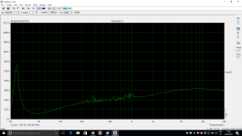
Maybe you forgot to mention in this thread that you are using a large inductor as a first order LP filter and you can't compensate its inductive reactance (Xl) just by inserting Zobel values,for example 9uF and 7 ohm. These can only compensate for the voice coil Le which is about 1mH at 1 kHz (SB23NRXS 45-8) and your values are ok for that matter but in order to see that in an impedance plot you'd have to remove the LP filter inductor. The only way to completely flatten the impedance is to place an RC filter before the LP filter ( directly in parallel with amplifier output) but that would not change one bit of loudspeaker SPL assuming you're using a typical constant voltage amp. So, the rise in impedance that you measure is normal. Zobel filters are usually good when there is a need to shape the response in a certain way to accomplish better summing at XO frequency.
Maybe you forgot to mention in this thread that you are using a large inductor as a first order LP filter and you can't compensate its inductive reactance (Xl) just by inserting Zobel values,for example 9uF and 7 ohm. These can only compensate for the voice coil Le which is about 1mH at 1 kHz (SB23NRXS 45-8) and your values are ok for that matter but in order to see that in an impedance plot you'd have to remove the LP filter inductor. The only way to completely flatten the impedance is to place an RC filter before the LP filter ( directly in parallel with amplifier output) but that would not change one bit of loudspeaker SPL assuming you're using a typical constant voltage amp. So, the rise in impedance that you measure is normal. Zobel filters are usually good when there is a need to shape the response in a certain way to accomplish better summing at XO frequency.
Attachments
Last edited:
Hi merlin el mago,
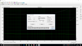
Before you run an impedance test in Limp, make sure you run a calibration test via the CAL button.
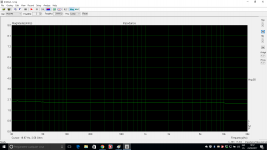
After that, measure the impedance of a resistor (for example 8.2 ohms metal film or metal oxide). If the response (in ohms and phase) is nice and flat, you can then be assured that your loudspeaker impedance measurements will be accurate.
If the response in ohms or phase are not flat, you may be able to correct this via the cable compensation button next to the CAL button.
Hope this helps.
Peter
")
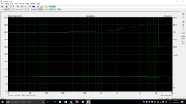
Thank you Peter, this is the best curve I can get with 10R 0,5% tol. metal film resistor, is OK for measurements?
Attachments
Hi Felipe!
Maybe you forgot to mention in this thread that you are using a large inductor as a first order LP filter and you can't compensate its inductive reactance (Xl) just by inserting Zobel values,for example 9uF and 7 ohm. These can only compensate for the voice coil Le which is about 1mH at 1 kHz (SB23NRXS 45-8) and your values are ok for that matter but in order to see that in an impedance plot you'd have to remove the LP filter inductor. The only way to completely flatten the impedance is to place an RC filter before the LP filter ( directly in parallel with amplifier output) but that would not change one bit of loudspeaker SPL assuming you're using a typical constant voltage amp. So, the rise in impedance that you measure is normal. Zobel filters are usually good when there is a need to shape the response in a certain way to accomplish better summing at XO frequency.
Measuremet only zobel 121uF + 8R2 without any kind of filter.
Attachments
Last edited:
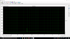
Measuremet only zobel 121uF + 8R2 without any kind of filter.
I don't think so. I agree with Lojzek. You have something else in the mix here and your Zobel measurements are not meaningful.
I suggest to start from scratch and make sure you're testing what you think you're testing.
Dave.
The object of using a Zobel network is to make the loudspeaker load purely resistive, which allows the crossover to work better, so you use Re as the value. The caps value is then calculated from R^2=L/C where L is the speakers inductance. This then will flatten the curve in your plot and note this impedance equalizer comes after the crossover.
Your measurements of a driver and a Zobel are unreal. Whatever you've placed in the impedance jig now reflects itself into the total Z magnitude. You have 8 ohm speakers with impedance in the range of 100 Ohms! That's obviously wrong. Go to ARTA thread and ask for help. The measurements of 10R and 2R2 resistors only shows that these ended up being okay.
Your measurements of a driver and a Zobel are unreal. Whatever you've placed in the impedance jig now reflects itself into the total Z magnitude. You have 8 ohm speakers with impedance in the range of 100 Ohms! That's obviously wrong. Go to ARTA thread and ask for help. The measurements of 10R and 2R2 resistors only shows that these ended up being okay.
Thanks. Do you have link to ARTA because using the search forum I only get a thread telling when a new release is coming.
The earliest reference that I have for the Zobel network formula is from a Philips/ Mullard book, "Transistor Audio and, Radio Circuits", circa 1969. It was given as a precaution against high breakdown voltages of output transistors that could be caused by an inductive speaker load. The formula given was Cz= Ls/Rs^2. Later clones of this calculation in an attempt to flatten a speakers' impedance use Rdc or Re x 1.25 in attempt to correct for the nominal impedance (Z) of the speaker to suit a crossover network design. By example using a Focal 7N313 where the D.C. resistance is given as 6.1 ohm and the inductance as 0.38 mH ( at 1 kHz ?) the first formula gives Cz as 10.21 mFd and the latter as 6.536 mFd. Using the method outlined in my first post the impedance at 3.5 kHz ( the desired xover freq.) was found to be 10.34 ohms with a phase angle of 28.65 degrees. This gives the effective resistance as 9.0742 ohms and the inductance as 0.2254 mH . Calculating for a network to give an impedance of 8 ohm with the phase at 0 degrees in conjunction with the speaker, resulted in values of 10.67 ohm and 3.69 mFd. It is a pity that many sources still keep quoting the wrong method of correction and so many people have been caught by this misapplied Zobel network.
Felipe, this is the thread.
http://www.diyaudio.com/forums/multi-way/76977-arta-55.html#post5000040
http://www.diyaudio.com/forums/multi-way/76977-arta-55.html#post5000040
- Status
- This old topic is closed. If you want to reopen this topic, contact a moderator using the "Report Post" button.
- Home
- Loudspeakers
- Multi-Way
- Zobel