I fail to understand why you need a Zobel on that driver, considering the fact that you want to cross it under 1.5KHz, and preferably under 1KHz. What Steve is saying is that not every RC across the driver is a Zobel. The TG crossover has a 2nd order electrical slope on the woofer, as is seen in many other designs - search on those in which you can see the values of the components.
Ralf
Edit: and example here: http://www.troelsgravesen.dk/3WClassic.htm
Ralf
Edit: and example here: http://www.troelsgravesen.dk/3WClassic.htm
It's not going to be wildly different from the 3 way classic. Just some allowance for the 4 ohm SB drivers and a second order tweeter, since it is more time aligned.
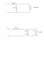
SEAS-3-Way-Classic
SEAS-3-Way-Classic

3.9mH with a 56uF and 1R
Not a bad choice, but there are plenty of similar ones which we might call "damped second order filter", nothing to see at all with what some would erroneously call a first order + zobel.
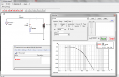
In most situations linearize the impedance curve is totally overkill, and you just need to fine tune the value of the resistor to "damp" this second order firter to a proper Q.
There are no magic formulas to get this done. You can use the Optimizer in Lspcad for that purpose: just define your target ( xover type point order slope and level), and you are done.
In this case ( i used your impedance data), it's better avoiding too low xover points like 200hz if you want to keep simple, but 400-500hz are easily achievable targets.
Attachments
@Lojzek
Re 3R7
This measurement is bad due to low battery, the right value is:
Re 5.39 ohms
Last edited:
Copper sheath over the centre pole.
The SB Acoustics speaker uses this copper cap method to minimise the inductive coupling of the coil to the iron components of the magnet assembly . This is clearly indicated in your Notebook readings and I would consider for this speaker that a correction network is not required if you choose a crossover frequency near 500Hz. I would consider that a conventional second order filter such as the Linkwitz Riley would be a better match considering the anomaly in the frequency response around 1kHz.
What will be the best xover point, when the phase is 0º 500Hz?
The SB Acoustics speaker uses this copper cap method to minimise the inductive coupling of the coil to the iron components of the magnet assembly . This is clearly indicated in your Notebook readings and I would consider for this speaker that a correction network is not required if you choose a crossover frequency near 500Hz. I would consider that a conventional second order filter such as the Linkwitz Riley would be a better match considering the anomaly in the frequency response around 1kHz.
Last edited:
No. It will be inaccurate unless it is a more complex instrument that can resolve vectors. You can derive L and R, from your Notebook readings as it supplies Z, phase angle (theta) and the frequency.It's safe to measure the woofer inductance with a LCR to know the Le?
Last edited:
Text Book Title ,magazine article,white paper?
I could not find a reference to learn what Mr. Woodgate has to say in detail about Re, Z or a Zobel. Can you confirm if it is the usual C=L/R^2 waffle.
My source for the correct way of using Zobel filters with passive crossover networks is from Mr. J. M. Woodgate B.Sc.(Eng.),C.Eng.,M.I.E.E., F.A.E.S.,F.Inst.S.C.E. and he states you use Re. For a filter without the Zobel, you would use the Z at the crossover frequency.
I could not find a reference to learn what Mr. Woodgate has to say in detail about Re, Z or a Zobel. Can you confirm if it is the usual C=L/R^2 waffle.
You haven't thought about it enough.Sure, i haven't found a single case in which a zobel was mandatory. In fact a zobel is simply an old fashion method to make simple things complicated...

It took me years to understand all the clever ideas in the old BBC monitor the Rogers LS5/9.
Rogers Loudspeakers › LS5/9
And the calculations aren't too hard:
mh-audio.nl - Home
You end up with a speaker with a delightfully flat impedance. Of course, feedback amplifiers shouldn't care about flat impedance. Except they DO! They hate extreme phase angle and low impedance. We know this, because they blow up in extreme cases.
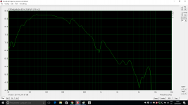
But VaNarn has got it right here. This SB Acoustics woofer is such low inductance, that it is scarcely worth correcting it:
The SB Acoustics speaker uses this copper cap method to minimise the inductive coupling of the coil to the iron components of the magnet assembly . This is clearly indicated in your Notebook readings and I would consider for this speaker that a correction network is not required if you choose a crossover frequency near 500Hz. I would consider that a conventional second order filter such as the Linkwitz Riley would be a better match considering the anomaly in the frequency response around 1kHz.
It sure goes to pieces above 1kHz, though. Not your well-behaved bass driver suitable for a two way.
And the calculations aren't too hard:
mh-audio.nl - Home
O.M.G, calculators...
So what we modern guys have access to sophisticated measurement / simulation tools for? Get back to the good old calculators days?
Imho, the way to go is get a set of frequency response / impedance measurement, chose a target and a circuit topology and check with your favorite cad tool if you can get some useful component values for the choosen target and topology.
Civilized drivers allow simplest topologies. This SB model is a piece of cake as a woofer provided you avoid using it as a mid-woofer, AND you cross it also high enough to avoid the influence of the impedance peak in the bass. Or will you try to hammer this flat too with some kind of mastodontic LCR stuff?
From the amp side, a civilized design is something that does not preferently require a resistive load.
Of course with vintage stuff like bextrene cones or valve amps, you might need old fashion tricks like zobels, etc...
Last edited:
Very complacent and patronising there, GDO. Clearly you not interested in learning stuff.
This ancient BBC LS5/9 revisited as the Graham Audio BBC LS5/9 is a pretty good speaker, by all accounts:
Journeys in Audio Subjectivism ? Part Five - Positive Feedback
I've learnt loads from it. It's genius. And hardly an expensive crossover.
Rogers Loudspeakers › LS5/9
This ancient BBC LS5/9 revisited as the Graham Audio BBC LS5/9 is a pretty good speaker, by all accounts:
Journeys in Audio Subjectivism ? Part Five - Positive Feedback
I've learnt loads from it. It's genius. And hardly an expensive crossover.
Rogers Loudspeakers › LS5/9
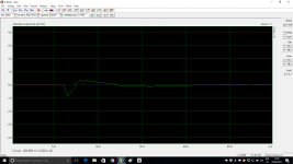
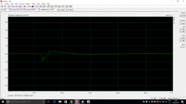
Today I have measured the FR of the two soundcards: M-Audio mobile pre vs VAIO internal.
An externally hosted image should be here but it was not working when we last tested it.
- Status
- This old topic is closed. If you want to reopen this topic, contact a moderator using the "Report Post" button.
- Home
- Loudspeakers
- Multi-Way
- Zobel