What Dcibel said.. 
Just don't use the servo circuit as I explained in the previous post. AFAIK no one is, so this should not be an issue. Use the circuit shown in post #301, the implementation of which is described in post #303 and others.
I have not, and will not post detailed information for implementing the servo as layout, power supply or some other issue prevents it from working properly when audio is present. It worked great on the bench, sounded odd in use, and was definitely generating audible distortion on peaks - like something was clipping. It was very late, I was out of time, and I unfortunately I didn't investigate as I would have had to set up a digital source on my bench. (Lazy and hungry No dinner until 11 last night.) I'm quite sure the problem would have been obvious had I really looked for it. I'm doubtful many would have been able to follow this path as the implementation was a real mess. I may post a picture at some point so you can see it.
Anyone capable of implementing it from the schematic will probably also have the skills required to troubleshoot it if they encounter the same issue I did.
I might try again with a carefully built outrigger board with a properly implemented servo circuit.
Just don't use the servo circuit as I explained in the previous post. AFAIK no one is, so this should not be an issue. Use the circuit shown in post #301, the implementation of which is described in post #303 and others.
I have not, and will not post detailed information for implementing the servo as layout, power supply or some other issue prevents it from working properly when audio is present. It worked great on the bench, sounded odd in use, and was definitely generating audible distortion on peaks - like something was clipping. It was very late, I was out of time, and I unfortunately I didn't investigate as I would have had to set up a digital source on my bench. (Lazy and hungry
No dinner until 11 last night.) I'm quite sure the problem would have been obvious had I really looked for it. I'm doubtful many would have been able to follow this path as the implementation was a real mess. I may post a picture at some point so you can see it.Anyone capable of implementing it from the schematic will probably also have the skills required to troubleshoot it if they encounter the same issue I did.
I might try again with a carefully built outrigger board with a properly implemented servo circuit.
Thanks Kevin. It wasn't clear to me that post 303 was with or without the servo changes. I'm glad to hear it did not include them or the problems you encountered.
It did puzzle me because the sound I am getting now is truly clear, clean, detailed and balanced. A very nice sounding DAC that perhaps only lacks a bit of texture that you find in the analogue domaine, or with the very expensive DAC's.
If you find a way to bring that into the equation (perhaps integrating a tube buffer stage?) I would be up for it.
Thanks again,
Bob
BobM said:Thanks Kevin. It wasn't clear to me that post 303 was with or without the servo changes. I'm glad to hear it did not include them or the problems you encountered.
It did puzzle me because the sound I am getting now is truly clear, clean, detailed and balanced. A very nice sounding DAC that perhaps only lacks a bit of texture that you find in the analogue domaine, or with the very expensive DAC's.
If you find a way to bring that into the equation (perhaps integrating a tube buffer stage?) I would be up for it.
Thanks again,
Bob
An interesting thought, were I to do this I would use 6021 sub mini tubes and make a board that fits the existing analog board foot print. The balanced voltage out configuration is a bit of a headache if you don't use transformers.
Power supply and transformer could sit in the space liberated by removing the headphone amplifier board. I'll think about it.


don't give up modding yet...
One well documented mod to digital section in cdps and dacs is to add small sheets of copper on top of ICs with in the digital section, and particularly over the controller ( the large dip chip). Strangely no one mentions this one in all the mods for the zhaolu. I had done it a while ago, but it is only yesterday i connected these "hats" together in star earth arrangement to the ground. you will be in for another surprise
My zap is a bit raised from the dac board due to space constraints, and it probably gets less sprayed with EMI like this...
if you want to isolate the controller even further, you will find that staples from an ordinary desk stapler seems to be almost made to measure for this, convering the legs of the ic too...just cut to lenght, ( could not be easier) the plastic ic support will prevent any short on the ic itself , just make sure it does'nt touch anything else on the board itself.
Re: don't give up modding yet...
Not really sure I understand your meaning here. Do you have a picture or can you describe this a little better for me? Sorry, but I can't picture what you're actually doing with the staple.
As for RFI/EMI, perhaps some of that ERS paper would work just as effectively. Usually it's put on the case top, but I don't know if you can put that right on top of the chips like your copper foil idea. I'll have to look into that. Do you know if Home Dopey sells copper foil?
Thanks,
Bob
C37 said:
if you want to isolate the controller even further, you will find that staples from an ordinary desk stapler seems to be almost made to measure for this, convering the legs of the ic too...just cut to lenght, ( could not be easier) the plastic ic support will prevent any short on the ic itself , just make sure it does'nt touch anything else on the board itself.
Not really sure I understand your meaning here. Do you have a picture or can you describe this a little better for me? Sorry, but I can't picture what you're actually doing with the staple.
As for RFI/EMI, perhaps some of that ERS paper would work just as effectively. Usually it's put on the case top, but I don't know if you can put that right on top of the chips like your copper foil idea. I'll have to look into that. Do you know if Home Dopey sells copper foil?
Thanks,
Bob
Hi Bob,
I cut pieces from a small sheet of copper (maybe 16x10 cms) bought from an art shop that is used for engravings: a bit thick to work ( 0.6 mm or maybe even more - use some sturdy scisors) but it's very very cheap. Shops who do model ships, airplanes etc are also a gold mine to find sheets of copper in different thicknesses... it's certainly cheaper than ERS paper.
I can make you pics but it's going to be late this evening...
If you have a stapler next to you, get a refill bar of staples. I am sure you will get the idea as soon as you have it in hand, just imagine it cut to the lenght of the controller ic ( the only dip one in the dac) - it forms a U shape, slide it over the IC ( think of a faraday cage) you'll see it fits really well. solder the earthing wire on the top side of copper first , glue the copper with clear double sided adhesive on the ic, slide the staple bar on top with just two tiny blobs of glue to secure it. don't try to solder the staples to the earthing wire, they're a pain. Maybe it's overkill using the staples on top of the copper so it it's up to you.
on the small smd chips i have just glued the copper with clear double sided adhesive, then solderred a wire to star earth on top.
Btw, do you have any pics of your trasfomer you put in the spdif rca? I would be interested in doing that mod, but not sure how to connect the pulse transformer...
Regards,
Thomas
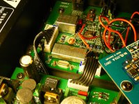
Here's the part # I got from Mouser: 673-PE-65612
There are 4 connections on it. I simply connected the + of the RCA to one and the through side of the pulse transformer to the board, and the - side of the RCA to the orher with the through to the board. A little hot glue stuck it to the board itself (it's fairly tiny). There's a good empty spot to the side of the RCA jack where it shouldn't interfear with anything else.
This one should also open your eyes a bit. It was a nice improvement. Lots of space and air with no digital grunge. I can't even listen to the TOSLINK connection anymore and, before this mod I thought it was better.
Bob
Hi Bob,
Thanks for the info.
You can get an idea here: http://didnt.doit.wisc.edu/audio/dddac1543/tweak_clock beads_and_47ohm.jpg
not taken from a zhaolu but the principle is the same. What i did is to put a row from a bar of staples on top of that, oriented towards the bottom of the board, thus covering the legs of the IC too.
BobM said:Here's the part # I got from Mouser: 673-PE-65612
There are 4 connections on it. I simply connected the + of the RCA to one and the through side of the pulse transformer to the board, and the - side of the RCA to the orher with the through to the board. A little hot glue stuck it to the board itself (it's fairly tiny). There's a good empty spot to the side of the RCA jack where it shouldn't interfear with anything else.
This one should also open your eyes a bit. It was a nice improvement. Lots of space and air with no digital grunge. I can't even listen to the TOSLINK connection anymore and, before this mod I thought it was better.
Bob
I would definitely agree, all of my sources are transformer isolated, the media server uses an external module I built a couple of years ago for this purpose - removing it makes an audible difference.
One other thing that is worthwhile is to add the copper foil lining in the chassis I mentioned in an earlier post. The chassis is steel - not a good conductor, and there is a lot of overspray present. The digital and power supply boards rely on the chassis to reduce ground plane impedance. I thought this was a worthwhile improvement. I will try some of the suggestions here, and in addition perhaps a faraday shield over most of the digital board would be worth investigating.
Question: could the spdif rca be somehow "contaminated" by emi radiation from the board itself ??
Since doing the copper on top of ic's mod, the rca seems to be at least on par with the toslink in my system, maybe slightly better ( mind you i just did that mod, at least this one does not need burning in, but i did not have much time to compare the 2 inputs since - what will be evident is the overall gain soundwise)
Question 2: anyway i need to change that rca, it's lousy like the one from the old audio boards. If i fit in a 75 ohm BNC, should i keep the 75 ohm resistor on the board or not?
Member
Joined 2003
I got a little exited when I got home with my parts order, so I went to town replacing parts last night. I should be able to give these changes a listed tonight, but in the meantime here's a bit on information on what I've done.
Power supply:
-lots of changes to the grounding arrangement. If I remember correctly the digital ground could only complete the circuit by passing through the chassis. I separated the chassis ground completely, and separated the ground plane at the two big caps. From each power supply circuit (two 5V supplies and analog +/- 15V supply) the ground has a single path back to the transformer through a wire.
-Chassis is connected to earth ground
-replaced all electrolytic caps. Smaller caps were replaced with Nichicon PW series 50V caps. The two big caps are Nichicon PW 35V. The two big 2200uF ELNA caps were replaced with Panasonic FM series 25V. Noticed that the G-Luxon cap installed on the board was a 25V cap with 25.5V on it. Yikes! I purchased a 25V Panasonic FM to replace it, but I put one of the ELNA 3300uF 35V caps here instead.
-replaced rectifier diodes with fast recovery schottkey type.
Digital board:
-removed all connections from ground to chassis.
-replaced 100uF tantalum caps on the analog 5V supply with 47uF Nichicon PW 50V caps.
Analog board:
-replaced 4 electrolytic caps in the supply with 2 Nichicon PW 50V caps.
-removed beads
-replaced op-amps with LM4562
-bypassed input coupling caps
-replaced the rest of the circuit with something similar to what Kevinkr designed. I added a bit to it to keep the transfer function close to the manufacturer's recommended filter. Resistors used for this are expensive Vishay CMF50 series, and caps are Panasonic ECQ-PZ (polypropelene).
-bypassed unneeded output buffer.
The only testing I've done so far is that I made sure the power supply still worked after all the track cutting I did to it.
Member
Joined 2003
My above changes are now complete, and the Zhaolu still works!
Obviously I'm going to say it sounds better, because it is better. How much better is hard to say since I cannot do a quick before and after test. My before was nearly a week ago. At the very least with the numerous cap changes I can be certain that my DAC isn't going to blow up any day soon.
Obviously I'm going to say it sounds better, because it is better. How much better is hard to say since I cannot do a quick before and after test. My before was nearly a week ago. At the very least with the numerous cap changes I can be certain that my DAC isn't going to blow up any day soon.


I Finally got a chance to put my modded Zhaolu 2.5C up against some strong competition. This DAC has been modded per post #303 and a few others here recommended by Kevin. It has the CD DAC chip in it and the 4562 op amps in the output stage.
I also replaced the power supply filtering with a "Felix" power conditioner, as described by Paul Kap on many threads at www.audiocircle.com. In fact, Paul was at this showdown and brought his Zhaolu 2.0 DAC along to compare also.
So, what did we put it up against? A Remyo CDP-777. We used this as the transport and just flicked back and forth between the 777 and the Zhaolu - a very easy compare. Here's a link to a 6-Moons review of this $17,000 CD player, which some reviewers think may be one of the best in the world:
http://6moons.com/audioreviews/combak2/cdp_3.html
So how did it fare? There were subtle differences, but in a nutshell I believe we all agreed that if we walked out of the room and back in again we wouldn't be able to tell which player was playing.
So, what were the subtle differences?
- There was a slightly better inner dynamic on the Reimyo, like the difference between f and ff or p and pp.
- The broad dynamics were pretty close with the Reimo having a better bass, which is where it manifested mostly. The Zhaolu was ever so slightly light sounding in the midbass and lower midrange, but that could also be the op-amps I chose, and so can be adjusted.
- There was a very slight veiling on the Zhaolu's. The leading "ting" of cymbals was not quite as sharp and pronounced.
- Also, the Reimyo had better decay of notes, letting them fade away more naturally.
Am I picking nits here? Yes, the differences were very subtle and probably not noticeable at all except that we had a direct A-B compare via a switch.
The bottom line, this DAC, which I have maybe $300 into, stood up incredibly well against a state of the art $17,000 player. Not bad for this little champ.
The difference between the 2.0 and 2.5C was even more subtle, with a bit more detail and transparency going to the 2.5C, but I'm sure Paul will be addressing this in his unit to bring them closer together.
All in all, both of us were very happy with the outcome, and the owner of the Reimyo was glad that there were differences, but with a $16,700 difference in price I think I'll stick with the Zhaolu for now.
Next discussion topic, are high $$$ digital players one of the biggest scams in audio?
Enjoy,
Bob
Thanks so much, Bob
I enjoyed reading your review. I've been deliberating whether to watch out for one of these Zhaolu's used. But at the same time, I am thinking about a Squeezebox type of setup with a large music server hard drive.
I thought someone felt that the dac's in the Squeezebox after some mods were pretty good. Just thinkin' out loud.
Thanks again for the comparison.
Lyndon
Salt Lake City
- Status
- This old topic is closed. If you want to reopen this topic, contact a moderator using the "Report Post" button.
- Home
- Source & Line
- Digital Line Level
- Zhaolu DAC - a good value DAC?