Hi there,
Thanks for the further info. Glad to hear progress and the pics.
Your bench is tidier than mine!
Best,
Susan.
Haha you haven't seen the floor. My cat likes my room. Lots of toys to play with.
...And I accidentally jammed my laser printer lol. "Open the rear and remove paper" Well it wasn't paper but a little bag containing some spare DN2540 mosfets!!!
Alfonso
Input transformers?
Which would you be referring to; line driver and/or power stage?
Best,
Susan.
are there cheaper input transformers for this amp?
Which would you be referring to; line driver and/or power stage?
Best,
Susan.
Alternate Power Stage Input Transformer for Testing
You could try the Hammond 124B Audio Interstage Transformer:
http://www.hammondmfg.com/pdf/124B.pdf
For something to get you going.
Best,
Susan.
for the power amp input trans
You could try the Hammond 124B Audio Interstage Transformer:
http://www.hammondmfg.com/pdf/124B.pdf
For something to get you going.
Best,
Susan.
Stee,
Why the link between the collectors of the 2SC3423s..... interesting circuit.
Hugh
Hug,
In the diagram, the collectors do not seem linked together
Roberto
Hug,Stee,
Why the link between the collectors of the 2SC3423s..... interesting circuit.
Hugh
I don't see link between the collectors of the 2SC3423s.
Roberto
Hi!
I read this at the Toroid Transformer version's page:
Greets:
Tyimo
I read this at the Toroid Transformer version's page:
What is the relationship to a larger VA input transformer and the 100 Ohm and 12V-5W zeners?Added R3 and R4 plus specified 5W zeners to maintain protection when used with larger VA rating input transformers.
Greets:
Tyimo
Hi!
I read this at the Toroid Transformer version's page:
What is the relationship to a larger VA input transformer and the 100 Ohm and 12V-5W zeners?
Greets:
Tyimo
I was being prudent about the amount of energy that can be driven forward from the proceeding stage when using a bigger VA input transformer.
These are mains power transformers and it's just to take care of this, for example if music is playing with the line driver on but the power stages are still off. Noting that even in this situation there will still be some sound coming out from the speaker.
Best,
Susan.
Thank you Susan!
I would have thought that for such a few mA what is in the signal a normal 1/2 or 1W zener is enough.
Greets.
Tyimo
Being prudent for something that is likely to be a bench lash up, not necessarily needed but I don't like to "pop" my mosfets
")
My Zeus Ver.2.0
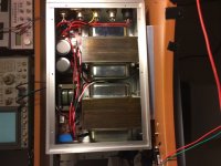
After long time I finally completed the reconstruction of my Zeus amp after finding impossible to reduce to an acceptable level the noise of 6c33c and replacing the tube with a mosfet.
The setup
Single-ended to Single-ended Mosfet driver at the input IXTP08N50D2 28V 430mA
Single ended - push-pull interstage transformer 1:10
Push-Pull power stage IXTH20N50D 34V 800mA each
Linear Phase Shift from 20 to 50KHz <2 degrees
It sounds amazing.
What first impressed me:
- Sound stage
- Fast
- Air
- Detail
and finally is totally quiet.
Attachments
Last edited:
Hi!
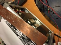
Could you give me some more details about your Single ended - push-pull interstage transformer 1:10?
Greets:
Tyimo
Hi,
I tried a few winding configurations and methods. I tried to do a perfect layer winding with 0.14mm wire under magnifying glass without crossings but it gave worse results in terms of bandwidth. The winding arrangement I attached worked best and the winding is just an easy one without layers. This gave best bandwidth results.
I hope it helps.
Attachments
Last edited:
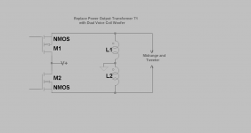
Post # 1 of this thread shows T1 power output transformer. The attached schematic suggests using a dual voice coil woofer instead of T1. Maybe this approach is already buried in one of the 1600 posts!
T1 is actually the input transformer. T2 is the output transformer through which each mosfet pull 750mA@34V from the C/T ground.
Are you sure you wanna do the same through the voice coil of the speaker?
Surely you will smoke it immediately. Besides a speaker is not a transformer nor a choke .
Susan quoted “An important thing to understand is that the output transformer's primaries swing negative as well as positive and the MOSFET for the half of the cycle which is negative is still powered but "idles" with most of the current flowing through the MOSFET going positive. However the negative arm MOSFET "WILL" regulate if something tries to overrun the main positive arm MOSFET position.”
I think the schematic would suggest to use inductors (or half transformer) instead of the transformer's primary and secondary. I remember Susan commented that particular circuit by connecting both mosfets and speaker on the primary of a transformer.
- Home
- Amplifiers
- Solid State
- Zero Feedback Impedance Amplifiers