I the last few days I spent a few hours trying to find out the source of noise in the amplifier.
I used 6c33c tube for line stage driver which gave me some hard time with the noise from the heater. Any noise in the line stage is amplified by 10 at the power stage so it must be quiet. At one stage I thought to give up the tube and try mosfet instead. Honestly the sound is different. My impression was that the mosfet sound was like dead compared to the tube. I have done a few tube vs mosfet listening tests back and forward trying to accept the mosfet but "no way!" .
So the first attempt was to switch to DC heater and the noise was reduced but not completely. The noise was like ground loop noise.
I short I find that it is important how the DC is connected to the tube probably because its physical construction and I find this way the best for reducing the noise to very low levels:
Pin 2 connected to Pin 6 (series)
Pin 1 Negative
Pin 6 Positive 12.6VDC from CRC filter
120Ohm Resistor between Pin 6 and Signal ground
I further reduced the noise in my system by changing orientation of the output transformer.
I am very addicted to the sound of this amplifier: the sound is very detailed, liquid, fast and.....
Last edited:
Noise - Sssssh!!! or Hummmm!!!
Hi,
So is this mains (line frequency) and it's harmonics pick-up, or white/pink noise?
Best,
Susan.
Hi,
I the last few days I spent a few hours trying to find out the source of noise in the amplifier.
I used 6c33c tube for line stage driver which gave me some hard time with the noise from the heater. Any noise in the line stage is amplified by 10 at the power stage so it must be quiet. At one stage I thought to give up the tube and try mosfet instead. Honestly the sound is different. My impression was that the mosfet sound was like dead compared to the tube. I have done a few tube vs mosfet listening tests back and forward trying to accept the mosfet but "no way!" .
So the first attempt was to switch to DC heater and the noise was reduced but not completely. The noise was like ground loop noise.
I short I find that it is important how the DC is connected to the tube probably because its physical construction and I find this way the best for reducing the noise to very low levels:
Pin 2 connected to Pin 6 (series)
Pin 1 Negative
Pin 7 Positive 12.6VDC from CRC filter
120Ohm Resistor between Pin 7 and Signal ground
I further reduced the noise in my system by changing orientation of the output transformer.
I am very addicted to the sound of this amplifier: the sound is very detailed, liquid, fast and.....
So is this mains (line frequency) and it's harmonics pick-up, or white/pink noise?
Best,
Susan.
SE depletion mosfet vs PP DN2535 line driver
Hi,
I haven't run the two side by side, so the comparison is remembered.
A version of the PP line-drive is being resurrected to drive rear amps in a 5.1 set-up though (but don't hold your breath please).
The SE depletion mosfet give a nice balance between SE front-end and PP power stage, and also importantly allows for a singe attenuator volume control.
If I was going direct from a digital source only, I would likely be using the DN2535 push-pull line driver.
Not quite the same, but this links to an old page that has a SE versus PP comparison.
Zeus Line Driver
The IXTH20N50D depletion mosfets, all other things being absolutely equal, have a slightly higher distortion than the regular mosfets; just enough to show up in measurements although I am not sure if it is audible being masked by the transformers, speakers and room acoustics.
The IXTH20N50Ds can be run with their gates referenced to ground for both the SE and PP configurations (with my EI120 transformers), which is a big plus and a number of people who have listened to my system have declared it to to be the best solid-state they have heard.
FWIW I had a full page review of my audio system by ex. editor Steve Harris in the November 2014 issue of HiFi News and Record Review (page 109).
Best,
Susan.
P.S. Both Digi-Key and Mouser show current stock for the IXTH20N50D parts (despite IXYS telling everyone a few years back that they were going obsolete). These do however vary widely in their spec's between individual parts (even the same date code) and I originally got 30 to select sets from. Probably 24 would be enough for a full stereo system with good matching sets for the PP power stages and near-ish matches for the SE line drivers.
Hi,
Hi Susan,
Could you please give me your listening impression of the single ended depletion mosfet preamp vs the DN2535 push-pull line driver?
I haven't run the two side by side, so the comparison is remembered.
A version of the PP line-drive is being resurrected to drive rear amps in a 5.1 set-up though (but don't hold your breath please).
The SE depletion mosfet give a nice balance between SE front-end and PP power stage, and also importantly allows for a singe attenuator volume control.
If I was going direct from a digital source only, I would likely be using the DN2535 push-pull line driver.
Not quite the same, but this links to an old page that has a SE versus PP comparison.
Zeus Line Driver
The IXTH20N50D depletion mosfets, all other things being absolutely equal, have a slightly higher distortion than the regular mosfets; just enough to show up in measurements although I am not sure if it is audible being masked by the transformers, speakers and room acoustics.
The IXTH20N50Ds can be run with their gates referenced to ground for both the SE and PP configurations (with my EI120 transformers), which is a big plus and a number of people who have listened to my system have declared it to to be the best solid-state they have heard.
FWIW I had a full page review of my audio system by ex. editor Steve Harris in the November 2014 issue of HiFi News and Record Review (page 109).
Best,
Susan.
P.S. Both Digi-Key and Mouser show current stock for the IXTH20N50D parts (despite IXYS telling everyone a few years back that they were going obsolete). These do however vary widely in their spec's between individual parts (even the same date code) and I originally got 30 to select sets from. Probably 24 would be enough for a full stereo system with good matching sets for the PP power stages and near-ish matches for the SE line drivers.
Hi,
So is this mains (line frequency) and it's harmonics pick-up, or white/pink noise?
Best,
Susan.
Thanks Susan for your reply,
There is no white or pink noise hissing at all and that's a big plus.
The noise was main with harmonics pick-up. I eliminated the noise from the heater by using 12.6VDC and arranged the heater series connection as I mentioned which made a huge difference. There is still a tiny noise I can pickup if I put my ear right next to the coil of the speaker. And that is like when you have an open ground, like humming with those harmonics. But the top is absolutely quiet.
Ground Loop?
Hi,
Could it be a ground loop? I know it's a over obvious thing but I find that they happen. One of the things I do on my pre/line-driver is switch the grounds as well as the signals (with an additional make before break switch segment).
Otherwise I guess simple magnetic field pick-up from somewhere. Can you take a mains transformer that is live (but obviously insulated in a plastic box - say a spare EI heater transformer) and move it around to see if the hum is increased or cancelled out?
Best,
Susan.
Hi,
Thanks Susan for your reply,
There is no white or pink noise hissing at all and that's a big plus.
The noise was main with harmonics pick-up. I eliminated the noise from the heater by using 12.6VDC and arranged the heater series connection as I mentioned which made a huge difference. There is still a tiny noise I can pickup if I put my ear right next to the coil of the speaker. And that is like when you have an open ground, like humming with those harmonics. But the top is absolutely quiet.
Could it be a ground loop? I know it's a over obvious thing but I find that they happen. One of the things I do on my pre/line-driver is switch the grounds as well as the signals (with an additional make before break switch segment).
Otherwise I guess simple magnetic field pick-up from somewhere. Can you take a mains transformer that is live (but obviously insulated in a plastic box - say a spare EI heater transformer) and move it around to see if the hum is increased or cancelled out?
Best,
Susan.
Hi Susan,
Happy new year.
I am still looking in detail for a way to improve the SNR. I got a question regarding the SE transformer. You mentioned about the quad-filar winding on each section of the former.
I found the best result only configuring SE in : SE out. Any attempt to configure SE-PP and I have lots of ringing and low bandwidth.
Here are the 16 wires out of the transformer: (S)tart (E)nd
S1A S2A S3A S4A -- -- E1A E2A E3A E4A
----------------------------------------------
S1B S2B S3B S4B -- -- E1B E2B E3B E4B
To take advantage of the capacitance I connected the winding in series in PSPS as follow:
GND—(E1B-S1B)—(E3B-S3B)—(E1A-S1A)—(E3A-S3A)—Source or K
GND—(E2B-S2B)—(E4B-S4B)—(E2A-S2A)—(E4A-S4A)—Out
This configuration gives perfect square wave with no ringing even unloaded and frequency response of this stage flat up to 700KHz.
The distortion also is very low.
How did you connect yours to get balance out? I was thinking to re-wind it for better SE PP result.
That was a reason why I had to package Line + Power together
Last edited:
Also with regards to the large input gate capacitance of the power stage which is 2500pF, assuming I am using 6c33c with S=40mA/V in cathode follower I have 1/S -> 25 Ohm output impedance. This impedance, excluding losses, is reflected at the gates of the power stage, on the secondary of the 1:10+10 step up transformer as 2500Ohm.
The current available also is around 30mA for the gates when 6c33c is at 300mA.
Driving 2500pF gates with 2500Ohm impedance would give the power stage frequency response up to around 23KHz according to RC formula.
I also checked with the scope and the predicted rolloff is correct.
Are you having different results?
Last edited:
Happy New Year to Everyone
Hi Apelizzo,
Thanks And to you and everyone here too. Lets hope 2015 is a better year (for me, 2014 was not so hot).
Okay, not quite sure why you are getting that...
In my line-driver with mosfet drive I have the two pairs of primaries (i.e. where each is wired one from each half) in parallel, with the secondaries being all in series.
I get the push-pull from putting the ground in the centre of the secondary set, so in the diagram above that would be:
-Out—(E2B-S2B)—(E4B-S4B)—GND—(E2A-S2A)—(E4A-S4A)—Out+
I also have a dual pole reed relay per channel that opens the two halves from ground, controlled from the mute position on the volume control (and so I always mute before turning off the power). This breaks the circuit to prevent power on/off thumps (and possible tears). Since they are at the ground point, there is no affect on the signal.
Overall gain is a little under 2x dues to the follower configuration..
For driving SE with a 6C33C I wired the primary's sections as you have shown above.
The other thing to double check is to wire one single winding only to a signal generator then with a say 100Hz signal go round all the other individual windings and check the polarity.
Best wishes,
Susan.
Hi Apelizzo,
Thanks
And to you and everyone here too. Lets hope 2015 is a better year (for me, 2014 was not so hot).Hi Susan,
Happy new year.
I am still looking in detail for a way to improve the SNR. I got a question regarding the SE transformer. You mentioned about the quad-filar winding on each section of the former.
I found the best result only configuring SE in : SE out. Any attempt to configure SE-PP and I have lots of ringing and low bandwidth.
Here are the 16 wires out of the transformer: (S)tart (E)nd
S1A S2A S3A S4A -- -- E1A E2A E3A E4A
----------------------------------------------
S1B S2B S3B S4B -- -- E1B E2B E3B E4B
To take advantage of the capacitance I connected the winding in series in PSPS as follow:
GND—(E1B-S1B)—(E3B-S3B)—(E1A-S1A)—(E3A-S3A)—Source or K
GND—(E2B-S2B)—(E4B-S4B)—(E2A-S2A)—(E4A-S4A)—Out
This configuration gives perfect square wave with no ringing even unloaded and frequency response of this stage flat up to 700KHz. The distortion also is very low.
How did you connect yours to get balance out? I was thinking to re-wind it for better SE PP result. That was a reason why I had to package Line + Power together
Okay, not quite sure why you are getting that...
In my line-driver with mosfet drive I have the two pairs of primaries (i.e. where each is wired one from each half) in parallel, with the secondaries being all in series.
I get the push-pull from putting the ground in the centre of the secondary set, so in the diagram above that would be:
-Out—(E2B-S2B)—(E4B-S4B)—GND—(E2A-S2A)—(E4A-S4A)—Out+
I also have a dual pole reed relay per channel that opens the two halves from ground, controlled from the mute position on the volume control (and so I always mute before turning off the power). This breaks the circuit to prevent power on/off thumps (and possible tears). Since they are at the ground point, there is no affect on the signal.
Overall gain is a little under 2x dues to the follower configuration..
For driving SE with a 6C33C I wired the primary's sections as you have shown above.
The other thing to double check is to wire one single winding only to a signal generator then with a say 100Hz signal go round all the other individual windings and check the polarity.
Best wishes,
Susan.
Hi Susan,
Thank you for your prompt help and support. Thanks also to everyone here.
I wired the transformer as you mentioned and it works well. Im still doing some tests...
I quickly compared the Line Stage alone with IXTH20N50D and 2SK1058. With 4 primaries in parallel the IXTH20N50D's self bias requires additional ~4Ohms in series with the transformer.
The 2SK1058 shows lower distortion. I didn't compare the sound yet.
Hi!
If I'm right in source follower mode you have to see the Crss value, what is much lower than the Ciss. For the SWT34B20 only 90pF!
Greets:
Tyimo
You are right according to the following:
Source Follower Amplifier Capacitance
"The input capacitance of a source follower configuration shown in Figure 1 is defined as the sum of the gate to drain capacitance, and gate to source capacitance multiplied by, 1 minus the gate to source gain, so:
Cin = CGD + CGS(1 - AGS)
Where: AGS = RS / RS + (1/gm) if the drain resistance is much greater then the source resistance as is often the case (rd >> RS)."
Last edited:
My Zeus rebirth
I'm finally getting some results (my ears are still ringing from the noise of the transformer ((0__0 )))
2SK1058 Mosfet SE:SE Line driver 300mA to SEP input power stage. Yes I built the 1:10 TX with winding optimised for SE connection.
The line stage transformer has 2 parallel P and 2 parallel S in series with the other 2 parallel pairs on the other half.
GND—(E1B-S1B)—(E1A-S1A)—Source
GND—(E2B-S2B)—(E2A-S2A)—Source
GND—(E3B-S3B)—(E3A-S3A)—Out
GND—(E4B-S4B)—(E4A-S4A)—Out
Tomorrow I will try 1324 instead of 1234
The 1:10 input TX does not like PP input unfortunately. The 4P parallel and 4S series worked on the line stage but caused lots of ringing on my 1:10TX so I have no choice but to connect in SE.
Vgs bias with floating 1.5V battery V adjusted for 300mA just for testing and added 6800pF capacitor (at hand) between G and S to stop oscillating.
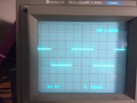
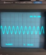
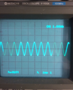
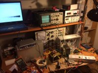
I attached pictures of 1KHz Square, 50KHz Sine and 1KHz Sine. There is little difference in amplitude between 1KHz and 50KHz....... and my messy bench.
I'm finally getting some results (my ears are still ringing from the noise of the transformer ((0__0 )))
2SK1058 Mosfet SE:SE Line driver 300mA to SE
P input power stage. Yes I built the 1:10 TX with winding optimised for SE connection.The line stage transformer has 2 parallel P and 2 parallel S in series with the other 2 parallel pairs on the other half.
GND—(E1B-S1B)—(E1A-S1A)—Source
GND—(E2B-S2B)—(E2A-S2A)—Source
GND—(E3B-S3B)—(E3A-S3A)—Out
GND—(E4B-S4B)—(E4A-S4A)—Out
Tomorrow I will try 1324 instead of 1234
The 1:10 input TX does not like PP input unfortunately. The 4P parallel and 4S series worked on the line stage but caused lots of ringing on my 1:10TX so I have no choice but to connect in SE.
Vgs bias with floating 1.5V battery V adjusted for 300mA just for testing and added 6800pF capacitor (at hand) between G and S to stop oscillating.
I attached pictures of 1KHz Square, 50KHz Sine and 1KHz Sine. There is little difference in amplitude between 1KHz and 50KHz....... and my messy bench.
Attachments
Last edited:
Hi there,
Thanks for the further info. Glad to hear progress and the pics.
Your bench is tidier than mine!
Best,
Susan.
I'm finally getting some results (my ears are still ringing from the noise of the transformer ((0__0 )))
...
I attached pictures of 1KHz Square, 50KHz Sine and 1KHz Sine. There is little difference in amplitude between 1KHz and 50KHz....... and my messy bench.
Thanks for the further info. Glad to hear progress and the pics.
Your bench is tidier than mine!
Best,
Susan.
- Home
- Amplifiers
- Solid State
- Zero Feedback Impedance Amplifiers