Member
Joined 2009
Paid Member
If you look at this, it's an input transformer set up as a voltage amplifier. It feeds a MOSFET set up as a Source Follower to provide current gain, the Source is loaded by the inductance of the output transformer which will give it good linearity. The output is taken from the output transformer so this is not a directly coupled output and you therefore you don't have to worry about dc offset or capacitors at the output.
Of course this isn't my amplifier so I could be wrong - at least I think I must be wrong because it looks as if the transformer must suffer the full dc current bias current flowing through the output MOSFET which means it can't be an ungapped transformer at the output - which was a benefit of the original balanced pp design.
Of course this isn't my amplifier so I could be wrong - at least I think I must be wrong because it looks as if the transformer must suffer the full dc current bias current flowing through the output MOSFET which means it can't be an ungapped transformer at the output - which was a benefit of the original balanced pp design.
Esactly That!
My Bi-Polar Darlington Transistor, Push-Pull version works exactly that way! My input transformers step speaker audio from the car head-end unit to about 9V RMS to drive each Darlington, Common Collector, operating at unity voltage gain, high current gain, to produce about 8A RMS to drive a 4ohm speaker through a step up, balanced autotransformer. Simple and effective, but expensive for use of iron.
If you look at this, it's an input transformer set up as a voltage amplifier. It feeds a MOSFET set up as a Source Follower to provide current gain, the Source is loaded by the inductance of the output transformer which will give it good linearity. The output is taken from the output transformer so this is not a directly coupled output and you therefore you don't have to worry about dc offset or capacitors at the output.
Of course this isn't my amplifier so I could be wrong - at least I think I must be wrong because it looks as if the transformer must suffer the full dc current bias current flowing through the output MOSFET which means it can't be an ungapped transformer at the output - which was a benefit of the original balanced pp design.
My Bi-Polar Darlington Transistor, Push-Pull version works exactly that way! My input transformers step speaker audio from the car head-end unit to about 9V RMS to drive each Darlington, Common Collector, operating at unity voltage gain, high current gain, to produce about 8A RMS to drive a 4ohm speaker through a step up, balanced autotransformer. Simple and effective, but expensive for use of iron.
You'll find this on Susan's site (link on first page of thread):
Zeus Amp - Schematics
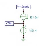
The first circuit is temperature compensated by the Mosfet. You can use a different current source for this too. You could do something like is done with temperature compensation for a SS amp VAS.
The second circuit is not temperature compensated, but will shut down if it gets too hot (first will also).
Sheldon
Zeus Amp - Schematics
The first circuit is temperature compensated by the Mosfet. You can use a different current source for this too. You could do something like is done with temperature compensation for a SS amp VAS.
The second circuit is not temperature compensated, but will shut down if it gets too hot (first will also).
Sheldon
Do you say, that this Vbias circuit put ca. 4-5 Vdc into the Gate through the secondary winding and thats all?
Yes.
")
Susan,
Can you advise where I can get IXTH20N50D mosfets? Do you have any for I can purchase from you?
Apparently there are many available from Hong Kong and China. Guess what, I sent a friend of mine in HK to check the part at the "presumed" seller and as he went inside the office everyone ran away leaving computers on desks etc. I think it was a scam's nest.
Hi Apelizzo,
Thanks for the info.
Whilst Ciss is specified a bit higher, I have not found it a problem.
The much greater simplicity plus having EVERYTHING ground referenced is a big plus.
The diferences sonically are very small, and I beleive would not cause unhappines.
It is relativly easy to try out both versions, would be interested to have your impressions if you do
My own system uses three IXTH20N50D per channel (pre amp is SE) and has been in almost daily use for something like four years.
Best wishes,
Susan.
P.S. slightly hasty lunchtime at work reply...
Susan,
Can you advise where I can get IXTH20N50D mosfets? Do you have any for I can purchase from you?
Apparently there are many available from Hong Kong and China. Guess what, I sent a friend of mine in HK to check the part at the "presumed" seller and as he went inside the office everyone ran away leaving computers on desks etc. I think it was a scam's nest.
Maybe we should all be made aware of who the scammers are?
Maybe we should all be made aware of who the scammers are?
The list of alleged scammers could be a long one. The price range for a IXTH20N50D is between 0.95 and 3.50 US$ each for 60pcs. Suspicious.
If someone wish to try, google the IXTH20N50D and find a broker, leave a "spare" email address and see what happens. Then you can play with them spamming each other with their own quotes until they give up.
Last edited:
IXTH20N50D mosfet availability
Hi Apelizzo,
Hope everyone is keeping well.
I have limited stock for my own use however I have asked for price and lead time from my original supplier (assuming they can get some).
Will get back to you as soon as I hear anything.
Best wishes,
Susan.
Hi Apelizzo,
Hope everyone is keeping well.
Susan,
Can you advise where I can get IXTH20N50D mosfets? Do you have any for I can purchase from you?
I have limited stock for my own use however I have asked for price and lead time from my original supplier (assuming they can get some).
Will get back to you as soon as I hear anything.
Best wishes,
Susan.
Building the Zeus
Hi Peter,
Sorry for the tardiness in replying, have been coping with life!
It is simple enough that if you are confident enough to build a mains linear regulated power supply you should be quite capable to build these.
The overriding issue of course is understanding and taking care to be sensible with any mains line side high voltage connections and wiring.
You could of course side step that one and run off two to four deep cycle 12V lead acid batteries, however one still has to be cautious as they pack a hell of a wallop if shorted out!
Safety first, last and all the way through.
The rest of the work is mainly deciding on the chassis style and how to mount the heatsink, and then drilling a few holes, bolting on a few components, and a few dabs of solder. Easy really!
Hope this helps.
Best wishes,
Susan.
P.S. And yes, I am building a phono pre for my cartridge. Lots of transformers of course however it does use C3g tubes triode strapped for the gain. It's still under development although I have got all the parts (sitting under my desk in a big box), now I just have to find the time to build the thing.
Hi Peter,
Sorry for the tardiness in replying, have been coping with life!
Dear Susan,
This is such a fascinating amplifier design.
With so few components, do you think a beginner could build it ?
And do you have a phono preamplifier design ?
Peter
It is simple enough that if you are confident enough to build a mains linear regulated power supply you should be quite capable to build these.
The overriding issue of course is understanding and taking care to be sensible with any mains line side high voltage connections and wiring.
You could of course side step that one and run off two to four deep cycle 12V lead acid batteries, however one still has to be cautious as they pack a hell of a wallop if shorted out!
Safety first, last and all the way through.
The rest of the work is mainly deciding on the chassis style and how to mount the heatsink, and then drilling a few holes, bolting on a few components, and a few dabs of solder. Easy really!
Hope this helps.
Best wishes,
Susan.
P.S. And yes, I am building a phono pre for my cartridge. Lots of transformers of course however it does use C3g tubes triode strapped for the gain. It's still under development although I have got all the parts (sitting under my desk in a big box), now I just have to find the time to build the thing.
Hello Susan,
Thank you for your reply. No need for any apologies at all! I'm sure that a talented engineer such as yourself would be in demand and kept very busy.
I must confess though, that I do blow hot and cold about my ability to build the amp but your post has enthused me!
Battery supply has the appeal not only for its simplicity but also for the immunity it would provide from the vagaries of London electricity.
I would also need to build a line driver. On your site, you have two designs - a single-ended version and a push-pull version, each use different input transformers. Apart from the input transformer, the single-ended version looks simpler, could this design be adapted to use the input transformer from the PP version?
Oh! And a stupid question - could I build the amp chassis out of wood? If so, then it would make the build easier, as drilling metal can be a pain, (unless you have a good vice or workshop. My London flat allows for neither.)
As my main listening source is LPs, (and BBC R3) I'm really interested and looking forward to the phono stage that you eventually come up with.
All the best
Peter
common drain v common source
Hi Joao,
To be biased, I think mine is better. But that is my preference and given that I have now been working on my transformer based follower amplification topology for the best part of two decades, probably my operant conditioning too.
Amongst other things in my topology the follower has below unity gain, therefore variations in load impedance etc. do not cause problems in the way a common source voltage amplifier does.
Also, unless one sets up as near identical circuits as possible, with mosfets, transformers and base topology (SE or PP) staying the same in both, one can't really make the absolute comparison between the two.
With mine, the low level "first watt" distortion is down at 0.005% THD for the whole amplifier i.e. pre and power stages (in 4:1 mode which is how I have my system setup). And that is without any global or local looped feedback, just the degenerative action of the followers.
Without naming names, someone who has been very active in the HiFi business (actually selling stuff for many years) told me recently that my system was the best solid state system he had ever heard. That was in his listening room, with his speakers, his normal CD player and his selection of music (although he did suffer to listen to a few of my fave tracks too).
Of course, this is all anecdotal, and at the end of the day the main attribute of any audio system is that you like to listen to it and can enjoy the music without being distracted by the sound quality or other artefacts.
The map is not the territory as one might say.
Best wishes,
Susan.
Hi Joao,
Hi Susan
I'm sure you have done listening tests between a common source stage and a source follower. Can you describe the sonic differences in your setup?
In my experience the sound of common source is more open and relaxed.
Thanks
Joao
To be biased, I think mine is better. But that is my preference and given that I have now been working on my transformer based follower amplification topology for the best part of two decades, probably my operant conditioning too.
Amongst other things in my topology the follower has below unity gain, therefore variations in load impedance etc. do not cause problems in the way a common source voltage amplifier does.
Also, unless one sets up as near identical circuits as possible, with mosfets, transformers and base topology (SE or PP) staying the same in both, one can't really make the absolute comparison between the two.
With mine, the low level "first watt" distortion is down at 0.005% THD for the whole amplifier i.e. pre and power stages (in 4:1 mode which is how I have my system setup). And that is without any global or local looped feedback, just the degenerative action of the followers.
Without naming names, someone who has been very active in the HiFi business (actually selling stuff for many years) told me recently that my system was the best solid state system he had ever heard. That was in his listening room, with his speakers, his normal CD player and his selection of music (although he did suffer to listen to a few of my fave tracks too).
Of course, this is all anecdotal, and at the end of the day the main attribute of any audio system is that you like to listen to it and can enjoy the music without being distracted by the sound quality or other artefacts.
The map is not the territory as one might say.
Best wishes,
Susan.
Hi Peter,
Yes, the power here is pretty awful. Tonight we have 246 Vac with 0.4 Vdc on it, that's enough to make standard toroid transformers hum audibly.
You could use the PP input for the SE, however then what about volume control?
I would suggest the Sowter 1035 Attenuator (with 6 dB Gain and Balance control. 48 dB in 2 dB steps plus 4 x 0.5 dB primary balance taps) as an alternative to the S&B TX102 as that is no longer available as separate components.
Wood breadboards should be fine. I used industrial steel wall boxes as I have to lug my stuff around for demos.
The phono pre is very much still in progress of preliminary building (still working out the best way to place everything) so it will be a while yet.
Best wishes,
Susan.
Hello Susan,
Thank you for your reply. No need for any apologies at all! I'm sure that a talented engineer such as yourself would be in demand and kept very busy.
I must confess though, that I do blow hot and cold about my ability to build the amp but your post has enthused me!
Battery supply has the appeal not only for its simplicity but also for the immunity it would provide from the vagaries of London electricity.
I would also need to build a line driver. On your site, you have two designs - a single-ended version and a push-pull version, each use different input transformers. Apart from the input transformer, the single-ended version looks simpler, could this design be adapted to use the input transformer from the PP version?
Oh! And a stupid question - could I build the amp chassis out of wood? If so, then it would make the build easier, as drilling metal can be a pain, (unless you have a good vice or workshop. My London flat allows for neither.)
As my main listening source is LPs, (and BBC R3) I'm really interested and looking forward to the phono stage that you eventually come up with.
All the best
Peter
Yes, the power here is pretty awful. Tonight we have 246 Vac with 0.4 Vdc on it, that's enough to make standard toroid transformers hum audibly.
You could use the PP input for the SE, however then what about volume control?
I would suggest the Sowter 1035 Attenuator (with 6 dB Gain and Balance control. 48 dB in 2 dB steps plus 4 x 0.5 dB primary balance taps) as an alternative to the S&B TX102 as that is no longer available as separate components.
Wood breadboards should be fine. I used industrial steel wall boxes as I have to lug my stuff around for demos.
The phono pre is very much still in progress of preliminary building (still working out the best way to place everything) so it will be a while yet.
Best wishes,
Susan.
- Home
- Amplifiers
- Solid State
- Zero Feedback Impedance Amplifiers