post94 has changed from two isolated supplies to a centre tapped supply.Gotcha,LM2941.Do I need a positive and Negative regulator for bipolar supply?
For this centre tapped supply you must use two opposite polarity regulators.
The previous post87 shows isolated supplies. That has the option to use either +ve, or -ve, or both polarities of regulators.
http://www.mouser.com/ds/2/212/KEM_LF0028_SS21V-1104206.pdf
Can I use this instead of R13 AND R14. making a CLC filter. Do I need two of these or two winding of one device will form an Inductor replacing R13 and R14.
Can I use this instead of R13 AND R14. making a CLC filter. Do I need two of these or two winding of one device will form an Inductor replacing R13 and R14.
It is a CMC, and it will saturate very early, a few tens of mA at most, if the currents are not compensated.http://www.mouser.com/ds/2/212/KEM_LF0028_SS21V-1104206.pdf
Can I use this instead of R13 AND R14. making a CLC filter. Do I need two of these or two winding of one device will form an Inductor replacing R13 and R14.
If you use it as intended, it will work as a regular CMC, which you don't need and is useless in your case, because of the GND connection.
Thus, completely useless for you
That saved me from a big mistake.what would be the example for an inductor that I can use to make a CLC filter? I am doing the wrong keyword search in mouser.is it the fixed indector?
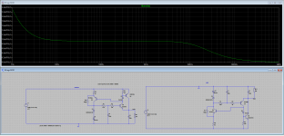
So my understanding is the current design has an attenuation close to 80dB for ripple , will it be worth taking the pain to add an LDO pre regulator ? Will it add more noise of a different kind to the supply ?
So my understanding is the current design has an attenuation close to 80dB for ripple , will it be worth taking the pain to add an LDO pre regulator ? Will it add more noise of a different kind to the supply ?
Last edited:
If you select single inductors, air or iron-cored, there will be no such ambiguity: their rated current will be ~their maximum operating current.Yup , but my question is more about finding an actual part, if it is about the inductor?
The larger the inductor, the larger the rejection, and also size and cost. The choice is yours.... (if you follow that route, which may not be the most advantageous)
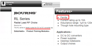
There are plenty of quite beneficial inductors for this application, which do not have an air core. One example, that I happen to have lying around on my bench, is (this) ferrite core inductor made by Bourns. Its inductance is 33 millihenries, its max DC resistance is 80 ohms, and its max DC current is 30mA.
I repeat: this is a ferrite core inductor. It is NOT an air core inductor.
Nevertheless, the manufacturer says it is ideally suited for DC to DC converter applications, where (as in linear power supply applications) the inductor current includes a very large DC component. See Figure 1 below.
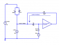
I built a little test setup to see whether this inductor misbehaves when carrying a DC current equal to (2/3rds) of its max rated current: 20mA out of a 30mA spec. My setup is shown in Figure 2. The inductor L1 forms a resonant "tank" circuit with capacitor C1; the resonant frequency is 1/sqrt(LC) = 174 kradians/sec (i.e. 27.7 kHz).
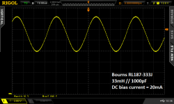
Then I measured it twice: first with the 20mA current source "I_BIAS" not connected, and then second with "I_BIAS" connected and pulling 20mA of DC current through the inductor.
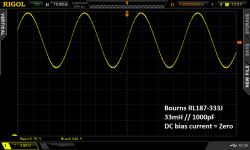
Results are shown in Figures 3 and 4 below.
We see that the resonant frequency did not change at all; therefore the inductance did not change at all. Whether carrying zero DC current, or (2/3rds of max rated current), the inductance remained rock steady.
For the curious: the current source was a bog-standard circuit using two 2N5551 NPN transistors and two resistors. Current equals VBE/Remitter and I used Remitter=33 ohms to get 20mA.
For the curious: the amplifier was a cascade of two CMOS logic gate inverters, from the CD4049UB integrated circuit. It runs quite happily on a 12V single ended supply.
edit: for the very curious: See whether you can figure out the DC resistance of the inductor by studying Figures 3 and 4. The inductor's datasheet guarantees that DC resistance will always be 80 ohms or less; but what is the actual resistance of this particular unit?
_
I repeat: this is a ferrite core inductor. It is NOT an air core inductor.
Nevertheless, the manufacturer says it is ideally suited for DC to DC converter applications, where (as in linear power supply applications) the inductor current includes a very large DC component. See Figure 1 below.
I built a little test setup to see whether this inductor misbehaves when carrying a DC current equal to (2/3rds) of its max rated current: 20mA out of a 30mA spec. My setup is shown in Figure 2. The inductor L1 forms a resonant "tank" circuit with capacitor C1; the resonant frequency is 1/sqrt(LC) = 174 kradians/sec (i.e. 27.7 kHz).
Then I measured it twice: first with the 20mA current source "I_BIAS" not connected, and then second with "I_BIAS" connected and pulling 20mA of DC current through the inductor.
Results are shown in Figures 3 and 4 below.
We see that the resonant frequency did not change at all; therefore the inductance did not change at all. Whether carrying zero DC current, or (2/3rds of max rated current), the inductance remained rock steady.
For the curious: the current source was a bog-standard circuit using two 2N5551 NPN transistors and two resistors. Current equals VBE/Remitter and I used Remitter=33 ohms to get 20mA.
For the curious: the amplifier was a cascade of two CMOS logic gate inverters, from the CD4049UB integrated circuit. It runs quite happily on a 12V single ended supply.
edit: for the very curious: See whether you can figure out the DC resistance of the inductor by studying Figures 3 and 4. The inductor's datasheet guarantees that DC resistance will always be 80 ohms or less; but what is the actual resistance of this particular unit?
_
Attachments
Last edited:
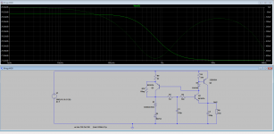
Wondering why the scale in this plot is only up to 100Hz ,should it not be upto 100Khz?To improve the line regulation, you can use this simplistic fix: just replace the jFET CCS with a banal BJT CCS, and you gain 40dB of static line regulation.
The higher frequency behavior remains unchanged because ultimately it is dictated by the Early effect of the transistors.
Note that this mod will also greatly improve the load regulation.
R10 is required to make the circuit start by itself, but it degrades the performances only very slightly
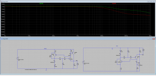
I was playing with your spice file Elvee, adding different transistors. It look better than original configuration to me. Is the attenuation =PSRR?
Attachments
Last edited:
Because at the time, you asked for a way to improve the line regulation, meaning frequencies close to DC.Wondering why the scale in this plot is only up to 100Hz ,should it not be upto 100Khz?
You can extend the plot to 100KHz, the changes should be minor.
Only at much higher frequencies will secondary effects appear.
Yes. It looks better, probably because the Early effect of your transistors is improved, to the extent that it even "drowns" the increase at VLF seen with mine.I was playing with your spice file Elvee, adding different transistors. It look better than original configuration to me. Is the attenuation =PSRR?
It is also due to the fact that the compensation of Q4 wrt. the other components is less favorable, leading to a diminished cancellation.
It is unimportant anyway, because it will remain better than with the jFET CCS
measurements
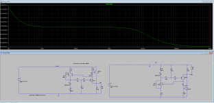
with both positive and negative supply PSRR. Negative supply PSRR is matching the TPS7A33. Is it accurate?
And noise figures if I am calculating right is better too in nV vs uV?is it real
with both positive and negative supply PSRR. Negative supply PSRR is matching the TPS7A33. Is it accurate?
And noise figures if I am calculating right is better too in nV vs uV?is it real
Attachments
Last edited:
Sipex makes an extremely low-noise version of the TL431 that is pin compatible with the TI device. _
Sipex merged with EXAR in 2007 if I am not wrong.
The SPX431 that is now sold under EXAR no longer specifies noise spectrum.
And the TO92 versionseems to be end of life.
The TL431 from TI is specified at 120nV/sqrtHz.
That from Diodes is at 220nV/sqrtHz.
The best I can find seems to be from On Semi at 50nV/sqrtHz.
Patrick
In 14 years I have seen this forum shine at some times. Now there is a lot of shame. This text file is rescued from the forum shining times, it compares noise of zeners, LEDs, TL431 and other elements. BZX55-C6V8 zener at high bias is a few times noisier than TL431 with gain for 6V output. I hope no one here has seen reverse biased diode noise in oscilloscope, it's really dirty.
I've made noise generators just amplifying noise of a reverse biased junction.
Hilarious. The file proposes that a bzx85-C12 is less noisy than a C2V7.
The 2V7 is a true Zener, the 12V is an avalanche diode and must be _much_ noisier.
Compare that to my own measurements at
< Zeners | Zeners have a bad reputation as being noisy. That i… | Flickr >
0 dB = 1nV/rtHz
You can clearly see that with rising voltage in the same family/technology,
the noise performance quickly worsens. Below 40 Hz, the better objects might
be even better because the preamp coupling C should be larger.
To the left and the right of that picture are the results of some further
interesting devices, among them a filtered LT6655 and the LT3042.
I also question that any bandgap can hold the candle to a low voltage Zener.
After all they do nothing but amplifying small voltage differences.
The LT6655 is quite a progress.
Gerhard
(currently in the north-west of Iceland in a hotel)
Last edited:
There is no "negative 3042" that I'm aware of.
Noise of references adds up, but only geometrically.
4 Zeners in series feature only twice the noise voltage,
so it is a better deal than amplifying by 4, which would
result in 4 times the noise voltage.
The geometric addition occurs because the noise
sources are independent, so the peak of one
MIGHT hit a valley of the other, partly canceling.
1. Yes.
2. It depends.")
On input voltage, output voltage, output current, Zener current..
The power input side should look like a current source, so that
the output impedance is dominated by the Z -diode.
So, the question can be reduced to "how much voltage does
my current source need to work properly?"
You can approximate the current source by a voltage source
and a series resistor. If your output current is large or your input
voltage is small, that will result in a small resistor, so the output
voltage is nearly connected to the input voltage. That will spoil
the improvement by the diode. It's all just simple Ohm's law etc.
2. It depends.
On input voltage, output voltage, output current, Zener current..
The power input side should look like a current source, so that
the output impedance is dominated by the Z -diode.
So, the question can be reduced to "how much voltage does
my current source need to work properly?"
You can approximate the current source by a voltage source
and a series resistor. If your output current is large or your input
voltage is small, that will result in a small resistor, so the output
voltage is nearly connected to the input voltage. That will spoil
the improvement by the diode. It's all just simple Ohm's law etc.
Last edited:
- Status
- This old topic is closed. If you want to reopen this topic, contact a moderator using the "Report Post" button.
- Home
- Amplifiers
- Power Supplies
- Zener+Voltage follower