Apassgear, thanks a lot for elaborating on R1. I will have to meditate a bit on your suggestions and try to incorporate your thoughts in the .sch this monday! I am quite dissappointed about myself, not sending the file home. I doubt I will have time to draw it all again this weekend. I would love to post a nice schematic of this amp though") Might be usefull for some people, I hope
Might be usefull for some people, I hope
My Zen is built with the original Pass Labs boards Yours look pretty good to me, but if the heatsinks arent up to the job.... too bad. I intend to make a hole new chassis with these heatsinks, I think they will do allright 8,7 kilo's a piece What do you think?
Steen
Might be usefull for some people, I hope My Zen is built with the original Pass Labs boards
Yours look pretty good to me, but if the heatsinks arent up to the job.... too bad. I intend to make a hole new chassis with these heatsinks, I think they will do allright 8,7 kilo's a piece What do you think?Steen
Attachments
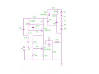
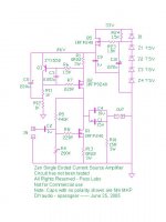
Vix said:Schematic seems fine, except one thing: R1. I would connect it directly to the Gate, as close as possible.
I have written before about my concern for the imput impedance. As I understood, we can put , say, a 22 KOhm resistor in front of C1 and then this circuit would have 22 K input impedance?
the 221 in series with the Zener makes it OK as you see it -
sometimes with the Zener directly at the gate you see some
parasitic oscillation, and placing some resistance in series
with the Zener takes care of that.
As to input impedance, it will be the Gate resistor to ground
in parallel with the 440K (dc feedback) divided by the gain,
and of course the capacitance of the Mosfet which 1,000 pf
or more. The less voltage gain, the less D-G capacitance.
Thanks, Nelson So the zener arrangement is ok. I just took R1 and put in place, where it sits in the ZenV1!
I guess this means I can let R1 sit where it does for now? Hope I am not being rude, asking that question?
Steen
So the zener arrangement is ok. I just took R1 and put in place, where it sits in the ZenV1!and so onAs to input impedance, it will be the Gate resistor to ground
I guess this means I can let R1 sit where it does for now? Hope I am not being rude, asking that question?Steen
steenoe said:My Zen is built with the original Pass Labs boards
With those sinks you can make 4 channels

Lucky you!!!
Yep, I do feel a bit lucky, with those heatsinksLucky you!!!
Guess what, I had them for soldering a preamp for a friend of mine. An OPA627/buf634 on PMA's boards Piece of cake
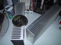
If I could just do more business like that The sinks measure like this: 400x200x85mm's! Quite heavy stuff
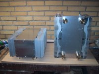
The body is 15mm's. Still they cant compare to the sinks I am using for my A-X. I am building monoblocks, 100 watt's. Have a peek at my not finished chassis's. I did manage to get 12mm faceplates for them. Thank's Magura
What do you think of those then Well, a bit brawling, I guessBTW I dont need 4 channels, I only listen to good old fashion stereo
Steen
Attachments
Those sinks look heavy, indeedThese are bigger than those...
What are those source resistors?? Seemingly, I am on an eternal search for suitable source resistors!Steen
Edit:
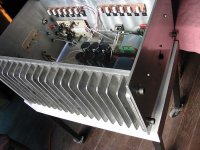
As Magura points out quite strongly, the fins have to sit on both sides of the body plateThese are bigger than those...
That will give you the most efficient heat transferring. Guess he's right about thatSource resistors are regular sand whiteis wire wound, nothing special.
The sinks were specialy casted for the Aleph4's. Never weight them but asume maybe more than 10 Kg each.
they mesure 260x560x70mm.
Magura is right, that's the best configuration but dificult to get on the size of interest unless you machine them, as magura does. But $$$$$...
The sinks were specialy casted for the Aleph4's. Never weight them but asume maybe more than 10 Kg each.
they mesure 260x560x70mm.
Magura is right, that's the best configuration but dificult to get on the size of interest unless you machine them, as magura does. But $$$$$...
Magura is right, that's the best configuration but dificult to get on the size of interest unless you machine them, as magura does. But $$$$$...
I just wonder if it is actually cheaper to water cool the amp. All the water cooling stuffs are pretty cheap on Ebay.
Nope, they are not machined! The ones, Magura use for his ZenV7, are machined, allrightMagura is right, that's the best configuration but dificult to get on the size of interest unless you machine them, as magura does. But $$$$$...
But only to fit his circular chassis I guess you need to have a Danish passport to get some of those sinks though Luckily enough, I do Well, to something totally different! I did search the Eagle libraries for a standard snap in cap, but couldn't find it. Does any of you guys know where I can find it??I need it for the outputcap, in case I actually make a pcb for this amp
Guess I will Steen
For me, the price is not a big concern. Nonetheless, I payed like some 280usd for 8 of those heatsinks. Well, I mean building a pair of "top of the shelf" amps will cost you some bucks.I just wonder if it is actually cheaper to water cool the amp. All the water cooling stuffs are pretty cheap on Ebay.
Whatever approach you care to take
Steen
I am just thinking out loud on these water cooling stuff. 80/20 is selling water cooling capable extrusions for like $8 a foot or something on Ebay. I think one can make the amp enclosure very small and incorporates a 3' long water cooling radiator into the amp rack. It will definitely have a different look to it.
I’m sure you could find those caps at Digy Key, I guess 15mf at 35V are good enough. But you don’t have a US passport!!! 
I will not mount the output caps on the PCB, the ones I will be using are some what big and come only at 4.7mf, so three of those plus a fat 10uf Wondercap.
Have already a design for the pcb for my very frugalphile way of doing them. Only one side, the other is mirror image so will require some working to accommodate the reversed pins of tranies.
agent.5 said:I am just thinking out loud on these water cooling stuff. 80/20 is selling water cooling capable extrusions for like $8 a foot or something on Ebay. I think one can make the amp enclosure very small and incorporates a 3' long water cooling radiator into the amp rack. It will definitely have a different look to it.
Some fellow members do have water cooled amps, such as Nelson Pass and GRollins and assume some others have experience on this way of sinking heat.
Does not appeal much to me, looks to cumbersome.
steenoe said:BTW I dont need 4 channels, I only listen to good old fashion stereo
But you do if you bi-amp
dave

- Status
- This old topic is closed. If you want to reopen this topic, contact a moderator using the "Report Post" button.
- Home
- Amplifiers
- Pass Labs
- zen without feedback