why not use a regulated supply to drop a few volts, and then use lower resistors to bring the bias back down? the case has some room to fit a additional heatsink for the regulator.
I can see maybe 43V------>CRCRC------>REG----->38V or so?
I would try that before I rebuild or purchase a new transformer.
Steve
I can see maybe 43V------>CRCRC------>REG----->38V or so?
I would try that before I rebuild or purchase a new transformer.
Steve
HIPCHECK said:why not use a regulated supply to drop a few volts, and then use lower resistors to bring the bias back down? the case has some room to fit a additional heatsink for the regulator.
I can see maybe 43V------>CRCRC------>REG----->38V or so?
I would try that before I rebuild or purchase a new transformer.
Steve
He has no reason to use a regulator.
All he needs is to find another heatsink, and he will need that with or without a regulator, as both solutions amounts to the same number of watts of heat.
Magura
")
Good luck and start low, build up. Monitor the current. I'd even start with 2x0.33ohms in series to start even lower.
What about the 40W lamp in series with the power cord trick? Is this a good safety net for birthing Papa's amps?
edit or 0.22 and 0.33 in series. I know you have parts for that!
What about the 40W lamp in series with the power cord trick? Is this a good safety net for birthing Papa's amps?
edit or 0.22 and 0.33 in series. I know you have parts for that!
ok so i got all the mosfets flipped around and they are new now. i also replaced the mpsa92's and installed them according to your pictures. i also replaced the input caps with 50v versions.
i also replaced the .33ohm R1's with .22ohm resistors to bring down the bias current.
im still in the same boat i was in before. it seems like the q1's arent getting biased or something, nothing is happening at all. nothing is getting warm and ive got 45volts at the drains and 345mv between ground and the gate of Q1 on one channel and .4mv between ground and gate of Q1 on the other channel. this curcuit looks to simple for me to be having all these problems......
please help
fligti91 said:does there need to be a 8ohm load or speaker connected for the circuit to operate normally?
No, it works without anything connected on both in and outputs.
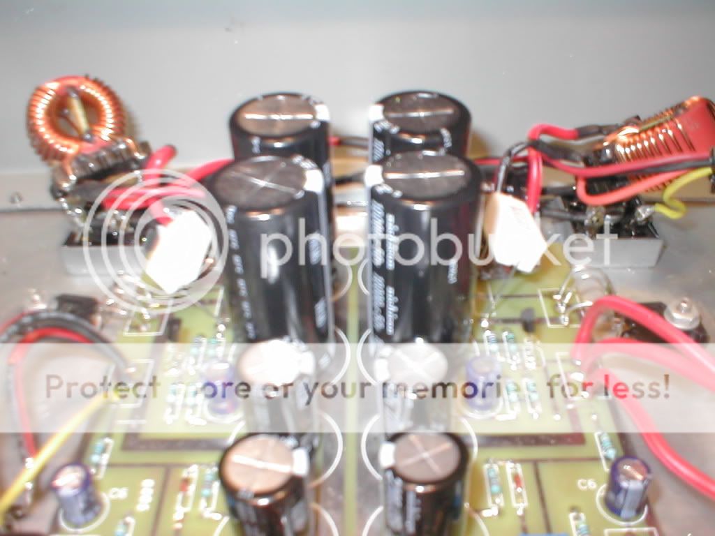
Please make a photo of things as they are now.
Magura
fligti91 said:ok so i got all the mosfets flipped around and they are new now. i also replaced the mpsa92's and installed them according to your pictures. i also replaced the input caps with 50v versions.
i also replaced the .33ohm R1's with .22ohm resistors to bring down the bias current.
im still in the same boat i was in before. it seems like the q1's arent getting biased or something, nothing is happening at all. nothing is getting warm and ive got 45volts at the drains and 345mv between ground and the gate of Q1 on one channel and .4mv between ground and gate of Q1 on the other channel. this curcuit looks to simple for me to be having all these problems......
please help
All your problems probably comes from the fact that Fig. 3A and fig.4 are flipped in the original article. This is how the component side (Fig.4) should have looked like.
Attachments
No you don't need a load.
So Q2 is hard on. (0V on gate, 45V on S & D). Which means Q3 isn't dong it's job of regulating the gate voltage. Check it's polarity, pinout and connection. Any solder shorts/dry joints? When it's working it will have 44.4V (45-0.6) on it's base and the collector should be rising up from 0V.
Then there's the question why there is 0V on gate of Q1, why isn't the resistor divider R6-P1 giving a voltage? Is P1 turned to 0ohms? is Z1 in backwards? Or is Q1 no longer a FET (and become a G-S short?)
P.S. get Q2 working first before you play with Q1 or you'll be popping fuses
Nelson Pass said:0 volts on the Gate of Q1 means no bias for Q1, and explains a lot.
What's happening with the resistors from Drain to Gate and Gate to
Ground? Is the input cap in place? Is the Zener backward or shorted?
I like to quote myself. As you can see, it adds spice to my conversation.
can you be more specific? i dont understand what you are trying to ask me.
i found earlier this evening that with the pot turned all the way counter clockwise that i had around .2mv at gate of Q1. with pot turned all the way clockwise i had 378mv at gate of Q1. another discovery today was that my heatsink is live. from ground to heat sink im showing 45 volts! any ideas?
i found earlier this evening that with the pot turned all the way counter clockwise that i had around .2mv at gate of Q1. with pot turned all the way clockwise i had 378mv at gate of Q1. another discovery today was that my heatsink is live. from ground to heat sink im showing 45 volts! any ideas?
- Status
- This old topic is closed. If you want to reopen this topic, contact a moderator using the "Report Post" button.
- Home
- Amplifiers
- Pass Labs
- zen v1 build problems????