
Hi Tortello,
I'd like to emulate your Headphone Amp. Could you please email me a pdf schematic. Does this include the zener protection diodes between R14-R15-R9-R6 and GND? I'm only a novice so it's not easily apparent to me where these should go. Also, what sort of VA rating should the transformer be??
Thanks very much for your help and sharing your circuit.
Joseph
(earjo951@student.otago.ac.nz)
tortello said:
Here the direct linkTortello's amp
Please, I'll be happy if you read the article and tell me what do you thinks.
Thanks for your advices!
Marcello
As much as I love headphones, I have to admit I have
been not giving this thread much attention.
Tortello, I think you should send your piece to AudioXpress
for publication; I'm sure Ed Dell would love it.
By the way, Grados are my favorite headphones, as long as
I don't mind hearing the rest of my environment. (then I
wear Sonys)

been not giving this thread much attention.
Tortello, I think you should send your piece to AudioXpress
for publication; I'm sure Ed Dell would love it.
By the way, Grados are my favorite headphones, as long as
I don't mind hearing the rest of my environment. (then I
wear Sonys)
Polarity Issue
Can't seem to wrap my head around this one!
Tortello's amp inverts polarity from input to output like the Zen V1-4 versions, and I would like to retain absolute polarity at the headphones in the similar version I am building to go with my Grado SR225's. My conscious mind is telling me to just invert the positive and negative connections at the output as Nelson shows in his schematics. But my subconscious mind is nagging at me that because headphones share a common ground connection for both channels this might cause a problem, and I should invert the connections at the inputs.
Is there a significant advantage to one method versus the other?
(This is a perfect example of why metallurgists should leave electronics alone!)
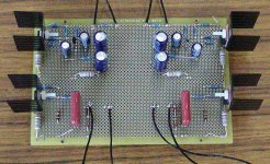
Moving Along - Old School Style
Stuffed a perfboard over the weekend and soldered it all point to point. Thought I'd share a pic. Waiting on delivery of a 50VA transformer from Plitron before I put together the power supply. Probably going overboard with the powersupply, giving it 24,000 uf of filter capacitance in a CRC arrangement, followed by separate regulator circuits for each channel. I'll post a pic of the PS once it's built.
Anyone going to bite on my earlier question, or was it just too plain dumb to warrant an answer?
Attachments
zen like headphone amp
Hello, I'm probably late but if you have the time I would love to get your schematic for the headphone amp as I have the same headphones.
Thanx again
telepod@email.com
Hello, I'm probably late but if you have the time I would love to get your schematic for the headphone amp as I have the same headphones.
Thanx again
telepod@email.com
Hello Norrin,
you can download all the project's files from the link paulb pointed out.
Hello Metalman,
you can test it by yourself inverting the headphone transducers connections: it seems that to disassemble Grados is possible, but I'm a little worried to do this.
Let us know about your impressions, if you decide to give it a chance.
Thank you.
Regards
Marcello
Hello,
I've found a source for OsCons here in the UK, but they do seem a bit limited for voltage. All the electrolytics on the schematic are rated at 25v, is this necessary or would lower values be OK? The ones Ive found are 100uF 20v, and for the output a single 1000uF 16v. Would these do the job?
cheers
Steve
all the info you are looking for can now be found here
http://headwize.com/projects/showfile.php?file=pellerano_prj.htm
Mark
http://headwize.com/projects/showfile.php?file=pellerano_prj.htm
Mark
ZEN headamp
Hi Tortello or anybody who can help me,
first thanks for your detailed description! I´ve build a pair of them and powered them with 24V Akku source. But the sound isn´t anything else than wide and clear. May be it depends on my headphpones? I use Ultrasone with a high impedance of 75 Ohms. The actual output current is about 130mA. Is it aproblem of the output impedance or what can i do?
Re: ZEN headamp
Try a better description of the sound ;
Chek if the input resistor value (R7) is correct .
baggerbole said:Hi Tortello or anybody who can help me,
first thanks for your detailed description! I´ve build a pair of them and powered them with 24V Akku source. But the sound isn´t anything else than wide and clear. May be it depends on my headphpones? I use Ultrasone with a high impedance of 75 Ohms. The actual output current is about 130mA. Is it aproblem of the output impedance or what can i do?
Try a better description of the sound ;
Chek if the input resistor value (R7) is correct .
To the Italian fraction
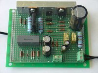
dear guys, that´s really not my first "freehand" builded circuit without a professional pcb, so we can exclude wiring and soldering mistakes to nearly 100% (nobody is perfect...)
And as I´m always still unsatisfied with the result of this job, I´ve done some additional measurements:
Outputlevel at 1kHz ->6Vpp, 10kHz ->5Vpp, 20kHz ->3,5Vpp
with 1Vpp input signal. AC level R10,R12 -> 8mVpp.
Instead of the ZTX450 i´ve used BD235 (hfe 40-160). I´ve tested different BC... with higher hfe, they made the circuit swing with MHz!
Give me a hint what to do.
Thanks and greetings from the German
Bernd
Attachments
I liked Tortello's circuit . It was playing with a 600 ohm Sennheiser HP
very well .
I know at headwize there are all the DC measurements that describes the circuit . So if you have around that values the circuit should be OK .
The mosfets can be demaged , also if they work.
Try pull up the active part of the current source and listen if someting
changes -disconnetting R8 or C3 .
If you used zeners , check the zeners .
Check if the output capacitor(S) are ok .
Remember that this circuit is phase inverting .
- Home
- Amplifiers
- Pass Labs
- ZEN-like headphones amp