Put a 1R resistor between DAC out and JFET source and use a differential probe to measure the current.
Then at least you know whether the right current is going in.
The other way you can check is use a fúnc gen and a resistor to simulate the DAC I_out.
Feed it to the IV and see what you get.
You need to trace current in and current out in the signal current loop.
The circuit is so simple. It has been built umpteen times.
How can it go wrong ?
Patrick
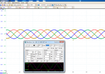
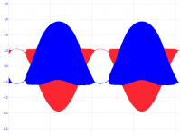
No IV cap, stoppers 100 ohm. It's visible by eye that the sine is distorted.
D.
Compression on the down swing. Is the supply symmetrical? Biasing?
OK,
I got it.
I added 47 ohm resistors between DAC and the jfets and used batteries for the reference instead of AVCC. Now it works very well.
One dump question: but putting a resistor between the DAC and the IV converter, doesn't the DAC see as load the value of the resistor + the impedence of the IV ?
Thanks,
D.
> but putting a resistor between the DAC and the IV converter, doesn't the DAC see as load the value of the resistor + the impedence of the IV ?
Yes, so bad idea.
Which was why I asked you to put 1R in between but only for the sake of current measurement.
The JFETs has a Zin of about 15R. Some other IV using BJTs has less. Opamp even less.
Patrick
Yes, so bad idea.
Which was why I asked you to put 1R in between but only for the sake of current measurement.
The JFETs has a Zin of about 15R. Some other IV using BJTs has less. Opamp even less.
Patrick
It works, but I do not understand: I have 633 mV RMS on the out with a 400 ohm resistor. I should have 3.2 V. Also it works also without the reference, just with Vref floating.
D.
If there is no difference with or without Vref connected, that's a dead give-away.
Jan
If there is no difference with or without Vref connected, that's a dead give-away.
Jan
You were right, as usual. sometimes the IV stop pulling current, and I do not understand what cause this. It's easy to spot, because the jfet get cold.
Anyway, now it seems to work, with no resistor between the DAC and the jfet and using the main power of the DAC as source of Vref.
One question: I understand that there is no current going in the Vref, so what's the reason for using 1K for the divider, instead of 100K ?
D.
- Home
- Source & Line
- Digital Line Level
- Zen -> Cen -> Sen, evolution of a minimalistic IV Converter