Subjectively AD1865 sounds much better.
Stunning was the word used for the AD1865.
But the front end is different (CS8416 SPDIF for 1794 vs Ultimate Source 2 for 1865).
So it is probably not a fair comparison.
At least we know it works for AD1865, PCM1704, ES9018, PCM1794, ....
And we might try AD1955 some time, but very low priority....
Patrick
Another R2R DAC win. Must build one.
Subjectively AD1865 sounds much better.
Stunning was the word used for the AD1865.
But the front end is different (CS8416 SPDIF for 1794 vs Ultimate Source 2 for 1865).
So it is probably not a fair comparison.
At least we know it works for AD1865, PCM1704, ES9018, PCM1794, ....
And we might try AD1955 some time, but very low priority....
Patrick
Patrick,
Are you using a digital filter with the AD1865, or are you using it NOS?
We took Calvin's advice and bought some NOS 2N4391 in TO-18 metal case.
Then we degenerated them to 6.2mA and measured current change with temperature.
The temperature gradient is about -3µA/°C.
Assuming a Riv of 680R, this means a tempco for the output DC offset of 2mV/°C.
Assuming your room temperature does not change more than 5°C, you are probably OK just using a single 2N4391.
Or if you are really clever, you can use an NTC in combination with fixed resistors for the degeneration.
")
Patrick
Then we degenerated them to 6.2mA and measured current change with temperature.
The temperature gradient is about -3µA/°C.
Assuming a Riv of 680R, this means a tempco for the output DC offset of 2mV/°C.
Assuming your room temperature does not change more than 5°C, you are probably OK just using a single 2N4391.
Or if you are really clever, you can use an NTC in combination with fixed resistors for the degeneration.
Patrick
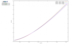
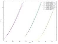
We made a fixture to mount the 2N4391 on our computer controlled heater block.
Then we curve traced a few examples at different temperatures from 25°C ~ 55°C.
The zero tempco current is at ~2mA, not 6mA as in datasheet.
You can always use 3x each degenerated to 2mA to make up the 6.2mA required.
Patrick
PS cannot upload any graphics to the forum.
Then we curve traced a few examples at different temperatures from 25°C ~ 55°C.
The zero tempco current is at ~2mA, not 6mA as in datasheet.
You can always use 3x each degenerated to 2mA to make up the 6.2mA required.
Patrick
PS cannot upload any graphics to the forum.
Sir,
I have a jpg of the data.
I have also plenty of previous experience uploading such files onto the forum.
But in the last hour or so, none of the numerous upload attempts I made went through.
Not by iexplorer, not by firefox, .......
Since I have no problem uploading files to other forums this evening, maybe the problem is not with me.
Cheers,
Patrick

Hi,
due to the negative Temp-coefficient one doesn´t need to worry too much as the bias point will stabilize whilst warm-up. There may be a slight offset from optimum for the warm-up time, but that dosen´t matter too for the output of the complete circuit.
In my SE-designs for the current sourcing DACs like PCM1792/94/95/96 I never had an issue with the current source not stabilizing at the desired bias.
So as long as the JFET is kept below its heat power limits, I see no real reason to use paralleled multiples of them, instead of a single one.
jauu
Calvin
Calvin,
In post #1586 above, we mentioned that the tempco at 6mA was -3µA/°C.
Assuming a Riv of 680R, this means a tempco for the output DC offset of 2mV/°C.
Or 10mV for an ambiet temperature change of 5°C.
So the issue was not stabilisation.
The issue was DC offset dependent on ambiet temperature.
In Asia and probably also in Southern Europe, room temprature change of 5~10°C is normal.
One can then argue whether 10~20mV offset is too much or not.
We just want to publish our findings.
One can decide for himself what solution he wish to choose.
The next thing we might wish to investigate is whether SMD devices behaves the same.
Best,
Patrick
Thanks Patrick - as one who has followed this from the beginning, the result is very interesting and it is a perplexing problem. Maybe SMD devices will behave differently, only experimentation will tell. Even a device (resistor for example) with a tempo of +3µA/°C would possibly not remain that way after 12 months or more…
Good luck and more solder to your iron! (or whatever aphorism is suitable)
bk
Good luck and more solder to your iron! (or whatever aphorism is suitable)
bk
If you want a long-term secured solution, then I suggest you use MAX6126.
There is a circuit to configure it as a current source in the datasheet.
And it is quite low noise.
For those who like living dangerously, 2N4391 is a good solution.
And there are enough variants being discussed to suit all tastes.
Patrick
There is a circuit to configure it as a current source in the datasheet.
And it is quite low noise.
For those who like living dangerously, 2N4391 is a good solution.
And there are enough variants being discussed to suit all tastes.
Patrick
- Home
- Source & Line
- Digital Line Level
- Zen -> Cen -> Sen, evolution of a minimalistic IV Converter