Sergio,
I think Calvin was referring to the current sink at the output of the PCM1794 to compensate for the 6.2mA offset current.
In that case the noise of that 6.2mA current sink is important, and will appear at the output.
In our current test circuit, we are using a single 2SK369V degenerated to give the 6.2mA required.
So both of you are right.
To rsavas,
The circuit is Sergio's intellectual property. So eventually he decides what to do with it.
But all XEN audio projects are, when offered to the public, published in every detail.
I hope that this will be the same.
This is not the appropriate time for publishing, as it is still being developed, discussed, tested, optimised, ....
When all that is done, and we think it is worthy of publishing, we will.
That is assuming Sergio agrees.
")
Patrick
I think Calvin was referring to the current sink at the output of the PCM1794 to compensate for the 6.2mA offset current.
In that case the noise of that 6.2mA current sink is important, and will appear at the output.
In our current test circuit, we are using a single 2SK369V degenerated to give the 6.2mA required.
So both of you are right.
To rsavas,
The circuit is Sergio's intellectual property. So eventually he decides what to do with it.
But all XEN audio projects are, when offered to the public, published in every detail.
I hope that this will be the same.
This is not the appropriate time for publishing, as it is still being developed, discussed, tested, optimised, ....
When all that is done, and we think it is worthy of publishing, we will.
That is assuming Sergio agrees.
Patrick
Sergio,
I think Calvin was referring to the current sink at the output of the PCM1794 to compensate for the 6.2mA offset current.
In that case the noise of that 6.2mA current sink is important, and will appear at the output.
In our current test circuit, we are using a single 2SK369V degenerated to give the 6.2mA required.
So both of you are right.
Patrick
Ops ... Sorry Calvin.
Yes for the 6.2mA current sink, is important to have a jfet with high source resistor value, for less noise at output. And as Calvin also says, is important that this ccs have high output impedance or the thd increase.
The 4391 for this position is a good idea.
I have try both jfet and bipolars, and I get the best results with a bc337 based ccs, realy very low noise, but I never try the 4391.
Have to buy some to test.
Hi,
The interesting part about the 4391 is its high idss of ~100mA.
That allows for a a large valued source resistor, making the ccs stiffer and less noisy. Paralleling devices to achieve suffuciently large dc-currents reduces Zout and increases noise again.
So I still think, that a single high Idss JFET is a prefferable choice.
jauu
Valvin
Calvin, with 4391, what is typically the value of the source resistor for 6.2mA?
Probably as much as 500R. See :
http://socrates.berkeley.edu/~phylabs/bsc/PDFFiles/2N4392.pdf
6mA seems also to be close to its zero tempco point.
BTW we just tested the 2SK369V with the PCM1794.
DC offset at the SEN IV output is stable to 1mV.
Patrick
http://socrates.berkeley.edu/~phylabs/bsc/PDFFiles/2N4392.pdf
6mA seems also to be close to its zero tempco point.
BTW we just tested the 2SK369V with the PCM1794.
DC offset at the SEN IV output is stable to 1mV.
Patrick
Hi,
The interesting part about the 4391 is its high idss of ~100mA.
That allows for a a large valued source resistor, making the ccs stiffer and less noisy. Paralleling devices to achieve suffuciently large dc-currents reduces Zout and increases noise again.
So I still think, that a single high Idss JFET is a prefferable choice.
jauu
Valvin
Now this is interesting.. I was not aware that using a large source resistor we would get a stiffer ccs.... and lower it's noise.... would you care to explain why ?
I am used to think in using lower Rs to lower noise in fet amps and paralleling devices to reduce noise... now this "new to me" concept is puzzling.... I know some of you might be thrilled by my lack of knowledge, but I am basically a mathematician, not an electronics wiz... please bear me.
There is voltage noise and there is current noise.....
Has being explained on the MPP thread many times.
The problem is that what is more or less self evident for a circuit designer may not be so clear for somebody who builds the stuff that we design.
That is exactly my problem.... this is a DIY forum, so you designers should be aware that there are some of us that build based on your ideas... hope I did not stir too much with my questions.
BTW, I need your help with the nobrainer
Please publish your questions about Nobrainer on the Nobrainer thread and i answer.
About know how : I had hoped that people are learning when they are building.
When I told you I needed your input, I already had published my question on the nobrainer thread... this was just a reminder hoping you would care to answer.
I see no point in building stuff if I do not fully understand the basics. Off course I learn by building... I did not study electronics in the university... I followed maths and if someone asks for my help I will always try to make it clear taking in consideration their flaws in algebra.... it is not possible to know everything all the time but we can always help if we want.
I do not think electronics to be an unreachable matter, I just need some hints here and there.
And most of all, I do not think those who learned how to design circuits to be more intelligent than others that learned how to design bridges.... can not grasp your bitterness.
The problem is that some here want to build the best with minimal outlay but they are not willing to study the circuit.
For example this problem with noise from the degenerated Fet.
It is the same then the noise contribution from the mirrors in the Paradise.
The higher the degeneration, the less is the CURRENT noise that is injected in the circuit.
That has being discussed and explained many time at least in my thread so i expect that somebody that reads the thread also reads the explanation.
I for one tried very hard to explain what i did.
That seems obviously ( more or less often ) not to be the case. Picking out the cherries is easy.
So how can there be even a basic understanding ? When it comes to pick expensive or exotic components then it gets into very different territory. Everybody seems to be an expert on this up to real hard core opinion.
I do not talk about you particular, Ricardo, you contributed even with optimizing the RIAA components and yes, my ability to design circuits makes me not more or less intelligent then somebody else that does other things better then me.
I am sorry I did not have the opportunity to follow your thread completely and so missed some important pints.
Anyway you made it very clear now and I see that Voltage noise increases with resistance and current noise decreases. For example, if you have a current mirror, and you wish the output to have low current noise you would be safe with a large resistor on the input side, since its current noise will be low. This large resistor will contribute a low amount of noise to the input, and thus the only noise you are left with at the output is the noise intrinsic to the current mirror itself.
As you see I am a fast learner.... just need some patience.
And I want to study the circuits and fully understand those before I adventure in building.
Last edited:
In the Paradise we found that the emitter resistors ( you call it input resistor, that are the resistors that go to the PSU ) should be more the 100 Ohm. Making them bigger then say 200 Ohm does not make a big difference any more. That resistor also has an effect on the output impedance of the mirror. Higher is better but there is also the issue of thermal drift so a compromise has to be found. I think that thoughts went into the current injecting Fet too and one that can be degenerated more to give the desired current is better when we bias that Fet into a region where it has a neutral drift.
In the Paradise we found that the emitter resistors ( you call it input resistor, that are the resistors that go to the PSU ) should be more the 100 Ohm. Making them bigger then say 200 Ohm does not make a big difference any more. That resistor also has an effect on the output impedance of the mirror. Higher is better but there is also the issue of thermal drift so a compromise has to be found. I think that thoughts went into the current injecting Fet too and one that can be degenerated more to give the desired current is better when we bias that Fet into a region where it has a neutral drift.
Yes, now I understand why the current injecting fets where so degenerated.
Also clearly understand the compromise choosing the 120r on the mirrors emitters.
I guess the source resistors in the output buffer serve the same purpose.
Ricardo, I will send you a email explaining
Thank you Sergio... looking forward to it.
PCM1794A
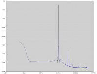
This is where I ended up with my Sen variant #998 (with 0R for RM) for PCM1794A described above:
Analyzing "mysensample.flac"...
Frequency: 999.977933 Hz
THD+N: 0.0009% or -101.3 dB
This THD+N is 20-700Hz+1300Hz-44.1kHz with 88.2kHz sample rate.
You can see from the spectrum that THD+N is mostly 3rd harmonic distortion at about -101dB, I'm guessing from the gate capacitance of the pair of JFETs which set the ground reference for the other JFETs in my circuit.
I'd be interested in seeing a measurement of your PCM1794 Sen version with the 2SK369V. Have you got any results from that yet? How does the sound compare to the other ones you have built?
Attachments
Subjectively AD1865 sounds much better.
Stunning was the word used for the AD1865.
But the front end is different (CS8416 SPDIF for 1794 vs Ultimate Source 2 for 1865).
So it is probably not a fair comparison.
At least we know it works for AD1865, PCM1704, ES9018, PCM1794, ....
And we might try AD1955 some time, but very low priority....
Patrick
Last edited:
- Home
- Source & Line
- Digital Line Level
- Zen -> Cen -> Sen, evolution of a minimalistic IV Converter